The preferred way to connect these boards to the consoles is via RJ45 connectors soldered to the board and then a console-specific connector soldered onto the other end of the cable. A few arcade parts stores sell premade cables for some of the more popular consoles at the time of this writing, but that will probably stop at some point, so it's good to know how to put these cables together.
There used to be a huge thread with really great tutorials on making these cables on the Shoryuken forums by user "rtdzign" but when SRK migrated to a different forum software a few years ago, it completely fucked up their post index so you can't get to things from google search results and I think the whole forum is shutting down completely soon, so all of this will be lost (most of it already is, really; I had to go sifting through the Wayback Machine's archives to collect most of this stuff).
Anyway, here goes (note: the pics in this post come from rtdzign's original tutorial on SRK and from Akishop Custom's PS360+ manual, with copyrights for those respective images belonging to them):
If you buy a MC-Cthulhu from somewhere, you may want to make sure you have the latest firmware. Toodles' "Godlike Controls" site has been down for a while, but the Wayback Machine cached the firmware file here.
Mirror
The ethernet connection pinout looks like this:

USB
The first cable you'll probably want to make is a regular USB cable (for PC and PS3). It's pretty simple - ground (pin 4 of the USB cable) goes to pin 1 of the ethernet cable, data+ (USB pin 3) goes to pin 5 of the ethernet cable, data- (USB pin 2) goes to ethernet pin 6 and VCC (USB pin 1) goes to ethernet pin 8.
Color - Purpose - RJ45 Pin - Cthulhu - ETH Color
Black - GND - 1 - G - Orange Stripe
--- - --- - 2 - A - Orange Solid
--- - --- - 3 - B - Green Stripe
--- - --- - 4 - C - Blue Solid
White - DATA- - 5 - D - Blue Stripe
Green - DATA+ - 6 - E - Green Solid
--- - --- - 7 - F - Brown Stripe
Red - VCC - 8 - V - Brown Solid
Original Xbox
Once you've done USB, OG Xbox is a logical next choice, as it's just USB with a proprietary plug:

OG Xbox also has a yellow wire that is unused and can be ignored, but otherwise it's the same as the regular USB cable.
NOTE: in general, don't trust wire colors blindly. *Always* test continuity with a multimeter to confirm wire-to-pin assignment. Cheap, knockoff extension cables are notorious for using essentially random wire colors (including nonsense like red GNDs, black VCCs, etc.)If your construction skills aren't great and you would rather buy something, I believe you could also just use a USB-female-to-Xbox-male adapter like this one (or build one) and get the same effect pairing it with your newly constructed RJ45-to-USB cable.
Once you've got the hang of it, the rest of the consoles are just a matter of matching up the gamepad pins with the ethernet wires.
Gamecube
Gamecube (not compatible with PS360+) only uses the first 3 pins of the controller, which makes it pretty easy: controller pin 1 is VCC, which goes to ethernet pin 8, controller pin 3 is GND, which goes to ethernet pin 1 and controller pin 2 is DATA, which goes to ethernet pin 7. Easy-peasy.Here's the diagram:

GC Pin - Purpose - RJ45 Pin - Cthulhu - ETH ColorAnd the same info in order of RJ45/Cthulhu pins:
1 - +5v - 8 - V - Brown Solid
2 - DATA - 7 - F - Brown Stripe
3 - Ground - 1 - G - Orange Stripe
GC Pin - Purpose - RJ45 Pin - Cthulhu - ETH Color
3 - Ground - 1 - G - Orange Stripe
--- - --- - 2 - A - Orange Solid
--- - --- - 3 - B - Green Stripe
--- - --- - 4 - C - Blue Solid
--- - --- - 5 - D - Blue Stripe
--- - --- - 6 - E - Green Solid
2 - DATA - 7 - F - Brown Stripe
1 - +5v - 8 - V - Brown Solid
N64

The Brook Retro Board has support for N64, and its pinout is very similar to the Gamecube's but in reverse order. That is, pin 1 is GND, pin 2 is Data and pin 3 is VCC (+3.3v).
N64 Pin - Purpose - RJ45 Pin - Cthulhu - ETH ColorAnd the same info in order of RJ45/Cthulhu pins:
1 - Ground - 8 - G - Orange Stripe
2 - DATA - 7 - F - Brown Stripe
3 - +3.3v - 1 - V - Brown Solid
N64 Pin - Purpose - RJ45 Pin - Cthulhu - ETH Color
1 - Ground - 1 - G - Orange Stripe
--- - --- - 2 - A - Orange Solid
--- - --- - 3 - B - Green Stripe
--- - --- - 4 - C - Blue Solid
--- - --- - 5 - D - Blue Stripe
--- - --- - 6 - E - Green Solid
2 - DATA - 7 - F - Brown Stripe
3 - +3.3v - 8 - V - Brown Solid
PS1 and PS2
PSX is another good one, since it covers both PS1 and PS2 and was considered the "standard" connector for sticks prior to the adoption of USB, so you can find PSX-to-whatever adapters fairly easily from companies like Raphnet. In fact, Akishop Customs recommends using a PSX cable with a PSX-to-Gamecube adapter to cover Gamecube and Wii inputs with PS360+ boards.Note: the 'RUMBLE' pin carries 7.2v-9v for use by the rumble motors. We don't need to mess with it.
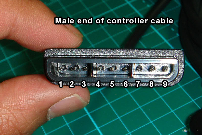

PSX Pin - Purpose - RJ45 Pin - Cthulhu - ETH Colorand here's that same data shuffled around to use the order of the RJ45/Cthulhu pins, in case that is easier to understand:
1 DATA - 4 - C - Blue Solid
2 CMD - 3 - B - Green Stripe
3 RUMBLE - --- - ---
4 GND - 1 - G - Orange Stripe
5 +3.3v - 8 - V - Brown Solid
6 ATTN - 5 - D - Blue Stripe
7 CLK - 2 - A - Orange Solid
8 UNUSED - --- - ---
9 ACK - 7 - F - Brown Stripe
PSX Pin - Purpose - RJ45 Pin - Cthulhu - ETH Color
4 - GND - 1 - G - Orange Stripe
7 - CLK - 2 - A - Orange Solid
2 - CMD - 3 - B - Green Stripe
1 - DATA - 4 - C - Blue Solid
6 - ATTN - 5 - D - Blue Stripe
--- - --- - 6 - E - Green Solid
9 - ACK - 7 - F - Brown Stripe
5 - +3.3v - 8 - V - Brown Solid
NES and SNES
SNES / NES is another interesting case insofar as they use the same protocol, just with a different connector. Rather than making/storing/transporting 2 separate ethernet cables, I made one ethernet-to-SNES cable and use a self-made SNES-to-NES adapter for NES (also useful for using the more ergonomic SNES pad on an NES). I also have a cheap SNES-to-Wiimote-expansion adapter (this one from Hyperkin https://www.amazon.com/Hyperkin-Controller-Adapter-Classic-super-nintendo/dp/B075RMYMNH) but neither my PS360+ nor my MC-Cthulhu work with my SNES Classic/Mini through it, so YMMV (worth noting: MC-Cthulhu and PS360+ don't work with my Analogue Super Nt using the normal SNES cable, either, though they both work with an actual SNES console, so clearly something fucky is going on that probably won't ever be resolved for either of the essentially dead products). I haven't tried either of them running through a Wiimote's Bluetooth connection (to, for example, use an arcade stick wirelessly with emulators on a softmodded Wii), so if you try that, please let me know your results in the comments.To be verbose, here are both the NES and SNES pinouts and pics, respectively (the "unused" pins are reserved for special controllers and serve no purpose for us):
NES

NES pin - Purpose - RJ45 pin - Cthulhu - ETH ColorAnd here it is sorted by RJ45 pin:
1 - GND - 1 - G - Orange Stripe
2 - CLK - 2 - A - Orange Solid
3 - LATCH - 7 - F - Brown Stripe
4 - DATA - 4 - C - Blue Solid
5 - UNUSED - --- - --- - ---
6 - UNUSED - --- - --- - ---
7 - VCC - 8 - V - Brown Solid
NES pin - Purpose - RJ45 pin - Cthulhu - ETH Color
1 - GND - 1 - G - Orange Stripe
2 - CLK - 2 - A - Orange Solid
5 - UNUSED - 3 - B - Green Stripe
4 - DATA - 4 - C - Blue Solid
6 - UNUSED - 5 - D - Blue Stripe
--- - --- - 6 - E - Green Solid
3 - LATCH - 7 - F - Brown Stripe
7 - VCC - 8 - V - Brown Solid
SNES


SNES pin - Purpose - RJ45 pin - Cthulhu - ETH ColorAnd sorted by RJ45 pin:
1 - GND - 1 - G - Orange Stripe
2 - UNUSED - --- - --- - ---
3 - UNUSED - --- - --- - ---
4 - DATA - 4 - C - Blue Solid
5 - LATCH - 7 - F - Brown Stripe
6 - CLK - 2 - A - Orange Solid
7 - +5v - 8 - V - Brown Solid
SNES pin - Purpose - RJ45 pin - Cthulhu - ETH Color
1 - GND - 1 - G - Orange Stripe
6 - CLK - 2 - A - Orange Solid
2 - UNUSED - 3 - B - Green Stripe
4 - DATA - 4 - C - Blue Solid
3 - UNUSED - 5 - D - Blue Stripe
--- - --- - 6 - E - Green Solid
5 - LATCH - 7 - F - Brown Stripe
7 - +5v - 8 - V - Brown Solid
TurboGrafx-16 / PC-Engine
TG16/PCE is kinda weird insofar as it has 2 functions on each pin (e.g. D-pad up and the I button) and then it uses the DATA SELECT pin to select which set of functions to poll.I don't have a TG16/PCE, but from rtdzign:
The American TurboGrafx-16 uses has a female Din 8 port on the system while the Turbo Duo and all the Japanese systems use a Mini Din 8. I recommend that you buy a number of 6 ft monoprice Mini Din 8 cables. For an TG-16 you can buy a male Din 8 connector and solder that to an ethernet cable.

And here's the diagram sorted by DIN pin:
DIN Pin - RJ45 pin - Cthulhu - ETH ColorAnd sorted by RJ45 pin:
1 +5v - 8 - V - Brown Solid
2 UP/I - 2 - A - Orange Solid
3 RT/II - 3 - B - Green Stripe
4 DN/Sel - 4 - C - Blue Solid
5 LF/Run - 7 - F - Brown Stripe
6 SELECT - 6 - E - Green Solid
7 OE - 5 - D - Blue Stripe
8 GND - 1 - G - Orange Stripe
DIN Pin - RJ45 pin - Cthulhu - ETH Color
8 GND - 1 - G - Orange Stripe
2 UP/I - 2 - A - Orange Solid
3 RT/II - 3 - B - Green Stripe
4 DN/Sel - 4 - C - Blue Solid
7 OE - 5 - D - Blue Stripe
6 SELECT - 6 - E - Green Solid
5 LF/Run - 7 - F - Brown Stripe
1 +5v - 8 - V - Brown Solid
Saturn
Saturn pads have voltage lines running in and out of the gamepad. When you see diagrams online, they are typically named according to the console's perspective, rather than the controller's, so keep in mind that these names are basically backward.
Sorted by Saturn pin:
Sat Pin - RJ45 pin - Cthulhu - ETH ColorSorted by RJ45 pin:
1 +5v-OUT - 8 - V - Brown Solid
2 DATA1 - 3 - B - Green Stripe
3 DATA0 - 2 - A - Orange Solid
4 SELECT0 - 5 - D - Blue Stripe
5 SELECT1 - 6 - E - Green Solid
6 +5v-IN - --- - --- - ---
7 DATA3 - 7 - F - Brown Stripe
8 DATA2 - 4 - C - Blue Solid
9 GND - 1 - G - Orange Stripe
Sat Pin - RJ45 pin - Cthulhu - ETH Color
9 GND - 1 - G - Orange Stripe
3 DATA0 - 2 - A - Orange Solid
2 DATA1 - 3 - B - Green Stripe
8 DATA2 - 4 - C - Blue Solid
4 SELECT0 - 5 - D - Blue Stripe
5 SELECT1 - 6 - E - Green Solid
7 DATA3 - 7 - F - Brown Stripe
1 +5v-OUT - 8 - V - Brown Solid
3DO
3DO pads have headphone jacks on them, so 2 of the pins are dedicated to carrying audio signals, and there's a second VCC line. I would assume you can use either of them but haven't tested it, since I don't have a 3DO. Neither did rtdzign, it seems, as here's what he had to say about it:(I don't have a 3DO and am assuming the D-sub follows normal pinout convention Picture is from a 3rd party genesis extension cable.)
3do will currently only work as the only controller, plugged directly into the system; trying to daisy chain off of it or use it through a daisy chain isn't going to work.

Here's the diagram sorted by Dsub pin:
Dsub Pin - Purpose - RJ45 pin - Cthulhu - ETH ColorAnd sorted by RJ45:
1 - GND - 1 - G - Orange Stripe
2 - VCC+5v - 8 - V - Brown Solid
3 - AUDIO1 - --- - ---
4 - AUDIO2 - --- - ---
5 - VCC+5v - --- - ---
6 - P/S - 7 - F - Brown Stripe
7 - CLOCK - 2 - A - Orange Solid
8 - GND - --- - ---
9 - DATA - 4 - C - Blue Solid
Dsub Pin - Purpose - RJ45 pin - Cthulhu - ETH Color
1 - GND - 1 - G - Orange Stripe
7 - CLOCK - 2 - A - Orange Solid
--- - --- - 3 - B - Green Stripe
9 - DATA - 4 - C - Blue Solid
--- - --- - 5 - D - Blue Stripe
--- - --- - 6 - E - Green Solid
6 - P/S - 7 - F - Brown Stripe
2 - VCC+5v - 8 - V - Brown Solid
Dreamcast
No VMU support and only works with games that can be played solely with an arcade stick. (update 8/4/23): Someone in the comments reported that the original pic was wrong, so here's a corrected pic:

The diagram was always correct:

DC Pin - RJ45 Pin - Cthulhu - ETH ColorAnd sorted by RJ45 pin:
1 DATA1 - 7 - F - Brown Stripe
2 VCC+5v - 8 - V - Brown Solid
3 GND - 1 - G - Orange Stripe
4 SENSE - 3 - B - Green Stripe
5 DATA5 - 4 - C - Blue Solid
DC Pin - RJ45 Pin - Cthulhu - ETH Color
3 GND - 1 - G - Orange Stripe
--- - 2 - A - Orange Solid
4 SENSE - 3 - B - Green Stripe
5 DATA5 - 4 - C - Blue Solid
--- - 5 - D - Blue Stripe
--- - 6 - E - Green Solid
1 DATA1 - 7 - F - Brown Stripe
2 VCC+5v - 8 - V - Brown Solid
Sega Genesis / Mega Drive
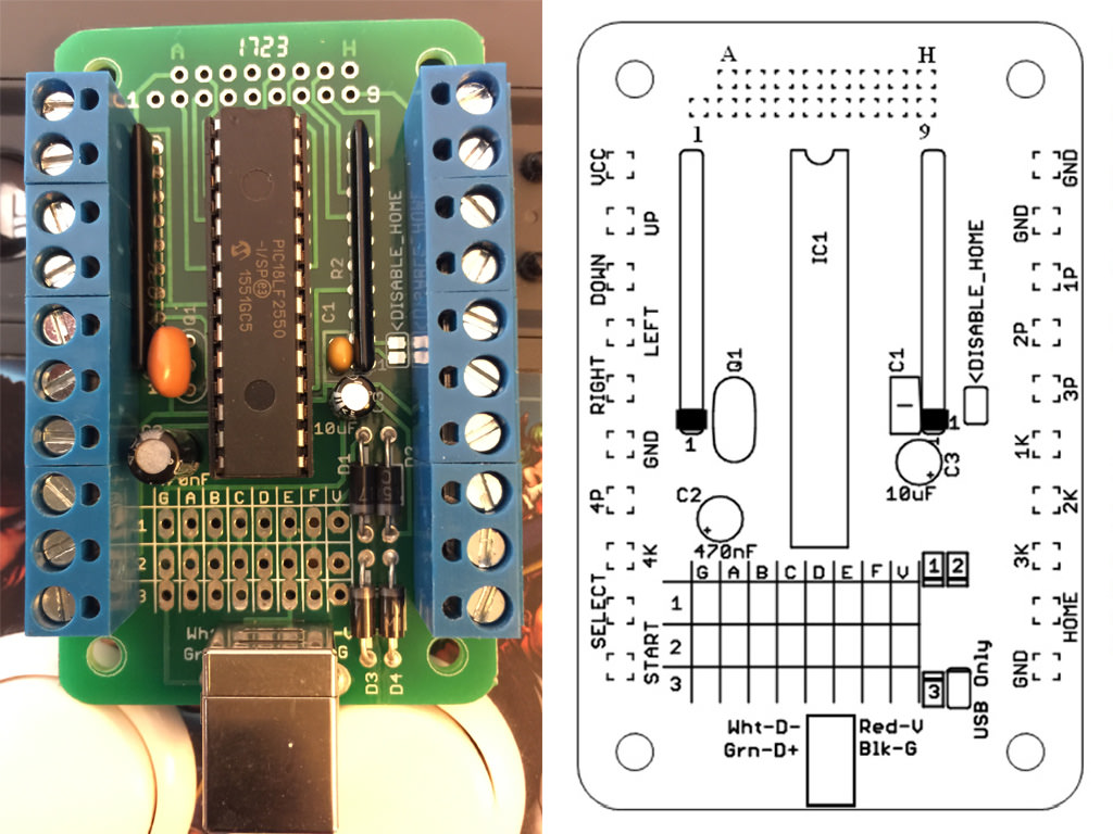
None of these boards work with Genesis / MD because it does its own crazy thing that's very difficult to reproduce without spending a ton of money on dedicated parts. The best thing to do for these is to padhack a crappy 6-button pad, which can be purchased online for peanuts. See my post here for a look at that process.MC-Cthulhu Secondary Solder Point Pinout
The Cthulhu boards include a double-row of unlabeled solder points on the side of the board opposite the RJ45 solder points. These are intended for attaching a 360 padhack for adding 360 support, but they're just additional hard-lines tied to the screw-terminals, so they can technically be used to add any additional PCB, so long as you tie the VCC and Grounds together.Since they're unlabeled, it can be a hassle to use them, but you can easily identify by testing continuity between the solder points and the screw-terms. Nevertheless, I'll include the pinout here to make it easier (the labeling scheme assumes right-alignment; that is, H and 9 are on the far right, lined up, while A and 1 are staggered on the left side):
[A] [B] [C] [D] [E] [F] [G] [H]
[1] [2] [3] [4] [5] [6] [7] [8] [9]
A = VCC
B = Down
C = Ground
D = Select
E = Right
F = 3K ('Roundhouse' in Street Fighter nomenclature)
G = 3P (Fierce)
H = 1P (Jab)
1 = Up
2 = 4P (PPP)
3 = Left
4 = 4K (KKK)
5 = Start
6 = 2K (Forward)
7 = 1K (Short)
8 = 2P (Strong)
9 = Home/Guide
And, just because I keep needing it and don't feel like searching for it every time, here's a copy of the MC-Cthulhu pinout:
40 comments:
Thanks for writing/recapping this info! Helped me a lot while trying to create my all-in-one stick. I was wondering if the MC-Cthulhu Secondary Solder Point Pinouts can be fitted with the wires from a Genesis PCB? If so, would you have to use the DB9 cable frome the hacked PCB, or would it be possible to use a CAT5-to-DB9 cable?
@Dennischz
Yes, you should be able to use the secondary points with a Genesis PCB. As for your second question, I believe you would need to use the hacked PCB's cable. Now, you could then hack that cable into *another* dedicated RJ45 jack, just for cleanliness, but you wouldn't be able to use the same one, as far as I know.
I'm actually working on something similar and my plan was to have just the connector/stub of the DB9 poking out of the stick and then use a Genesis/MD extension cable to actually attach that connector to the console. That way my stick doesn't have an ugly cable hanging out of it all the time. If your stick has a cable cubby, you could potentially hide it in there, as well.
I am able get most of the cables to work but no luck with Game cube controller. I am using Brooks retro board and trying to use my fight stick on wii using the gamecube controller port but no luck. I do see that board gets the power but no action at all !! Any help please.
Looks like you can purchase pre-made cables for it, so it's indeed possible:
https://jasenscustoms.com/products/retro-cable-rj45-to-gamecube-1?_pos=1&_sid=2cce52cfa&_ss=r
The pinout here seems to be correct, at least according to the only other source I can find online: https://forums.shoryuken.com/t/rj45-detachable-cables-how-to/57601
Since only 3 pins/wires are involved, I would suggest connecting the vcc and gnd pins and then just go through testing the other pins until you find one that works. If it's different from the one I mentioned in the post, let me know and I'll update the post!
I have the exact same prob. I have 2 retro boards and 4 gc cables. Any combination of PCB and cable has the same result my stick works for 2-5 seconds then stops responding. Cables tested with cthulu pcb work just fine. All other consoles work fine with the retro board.
Forgot to mention that 2 of the cables were crimped myself, the other 2 were purchased at Jasen's Customs.
@Hunter K - I saw you mentioned no VMU support in relation to the RJ-45 for the Dreamcast... and I have a related question I haven't been able to find a question to that maybe you know the answer to. I would like to add a Brooks Retro Board to a Dreamcast Agetec stick... do you know if there is any way to do that and still have the VMU slot function? Thanks
@SuperHamFists
Unless the Brooks Retro Board explicitly says it supports it, my guess would be no :(
LoL, I was lead to this blog from another website. I previously commented on your cheapo Sega padhack blog, but I think my questions would be better suited here since it is more MC Cthulhu related. I read your response towards me and it's sad to hear your results, but I will continue here.
Thanks man, good stuff reading on your blogs though. I'm doing more research to connect to the cheapo Sega pad to the MC Cthulhu. So far not really great, but I hope there will be a way. I already have a dedicated official Sega 6 button pad hacked stick but want an all in one self contained stick! Your posts have gave me enough interest to do so. Thank you man!
,Karcus
@Karkus
Yeah, I made a dedicated Genesis/MD stick, as well, but had really hoped to get it all working together, as well. I had wanted to solder my Mad Catz SE's control board into the secondary points on the cthulhu with a toggle to switch between them on the USB cable, with the Gen/MD padhack hanging out the back, but when I couldn't get the SE board working with the Cthulhu, I got bummed and haven't picked the project up since :(
I'm hoping to get back into it soon, though, and at least get the gen/MD+Cthulhu working. If I succeed, I'll make a post about it, as it seems I'm not the only one trying to do it!
I'm incredibly glad to see that you're still replying to comments on this post because boy am I incredibly frustrated with the situation I put myself in! Here's a tiny bit of background...
Wanted to use a Brook UFB's USB-B out to etherCON, then from there plugging into modern consoles. Figured I could take a USB-B to USB-A cable, cut the cable and slap some RJ45s on there, and make sure that each wire would line up with its counterpart on the other RJ45. However, it's nearly impossible to fit the ground and voltage cable into the RJ45 jack and I have yet to be able to actually get one to fit and make a complete connection with the board and my PC (checked with other non-tampered cables plugging the PCB directly into my computer, it works fine).
So basically, is there anything I can really do here? The only other idea I had would be to potentially cut the USB cable and a cat5 cable, solder the matching wires together, then cover the soldered area with some heat shrink. I'd rather not go this route if only because I'd rather not go out and buy a soldering iron, but shy of switching out the etherCON for it's USB-B passthrough counterpart (which I hear breaks easily and is exactly why I wanted to go the etherCON route) I'm not sure how to move forward here.
Thanks for any help or advice you can offer. Been asking around a few places and haven't had much luck.
@lame-o
Yes, cramming non-CAT cables into RJ45 connectors is no good. Cutting and splicing is much better, I think. While I think having and being comfortable with a soldering iron is a good thing, you can probably find someone who already has one and will either let you borrow one or will do the soldering for you.
If you decide to go that route, I would recommend getting a decent iron (the hakko fx-901 is pretty cheap and good/convenient for this sort of job), as crappy irons make everything more difficult. Also make sure you get leaded solder and don't skimp on the flux. Heat-shrink tubing will make a nicer-looking result but if it's just going to be locked up inside of a stick case, electrical tape is probably fine.
@Hunter
Thanks! I ended up finding some wider gauge RJ45s that fit USB wires which worked for a quick and dirty version, but I'm now looking to do it properly. I've got a soldering gun and looking to get some good solder and flux, but I have one last question.
If I'm going to be cutting and splicing a cat5 cable and a retro controller cable, how do I make it look good? I'm looking at the cables available through ArcadeShock and such and I can't see where the cables were cut, which is exactly what I want out of the ones I'm making.
My assumption is that the break between the two cables is extremely close to the RJ45 connector and therefore covered by the strain relief boot, but that method really leaves little to no room for error. Although if I'm crimping the RJ45 onto some bulk cat5, I guess it's no big deal if I have to snip off a little more and use another RJ45 if I mess up the soldering.
Anyway, I was hoping you might have some insight to offer on this, as I want to make sure I end up with a cable that I'm proud of.
Thanks!
The ones you buy from ArcadeShock et all are manufactured rather than hand-assembled, so they're always going to look better. If you're going to put a neutrik connector on it, that will make it easier to hide using the strain relief boot, as you guessed, but if you are just plugging it in bare, it is a lot harder. Personally, I just do it somewhere in the middle and try not to worry about it too much.
There are some tricks you can do to make the end-result neater, like this Instructable by Becky Stearns: https://www.instructables.com/id/Soldering-Clean-Wire-Splices/ but it's never going to look as good as a manufactured cable, unfortunately.
Is anyone aware if these RJ45 pinout cables will work with the Retropad32 adapter? I have many RJ45 cables for different consoles that work with my MC-Cthulhu arcade stick but I'd like to know if I can use those same RJ45 cables with the Retropad32.
I don't have it in my possession yet but when I do I believe the only thing to watch for is where the voltage pin is going if I'm to test if the cables work.
I was quite active on the shoryuken forums back then (from 2008 on) and was pissed that the most useful piece of information there was lost due to their transition to a newer forum.
I'm glad someone like you took the time to republish all the info/pictures of the original tutorial by rtdzign. So thank you and thank you also RTDZIGN
@speedsterharry
Hey, my pleasure. So much great info got wiped out with that transition (not to mention the flaky imageshack hosting); I'm glad I was able to save at least this one small piece before all traces of it were gone.
Do you have hd pix of the multi console rj45 cat5 cable tips?
I used this guide and took my time with a multi-meter to test for continuity.
I tried to make Dreamcast, GameCube and Saturn for the MC Cthulhu but they don’t work.
Am I missing something? Like a button combo? I thought they’d be auto detected.
The ps2 and USB ones I made work fine. Perhaps I need the cat 6 tips with the brace guide?
SNES don't work at all. Nes wire on an av famicom glitches up the game when I plug it in. my AVFC is modded to use USA nes pads.
If you look at Dreamcast guide here 2 pictures at the top of the dc section aren’t wired the same, followed the diagram and the text you wrote, not the photo of the controller end (top picture in the DC section). I think the DC controller port on one of my dc got blown out.
For NES, SNES (wire is Japanese, but i have always used Japanese pads on my snes mini), PS2 I am using official wires. DC, SAT, NGC I am using the ends of generic pads.
I have 2 MC Cthulu but I've only done these tests on one.
Thank you.
I haven't personally built Dreamcast, Gamecube or Saturn cables, but I have built NES and SNES cables and they are definitely correct.
You're right that the Dreamcast images are indeed different. The top one is from rtdzign original tutorial on SRK, while the diagram image is from Akishop's documentation. PS360+ and MC-Cthulhu are supposed to have the same pinout, but something's obviously not lining up on that one. Would you mind checking on your DC console's controller port which pin is VCC? That should hopefully tell us which diagram is correct.
There shouldn't be any way to burn out the DC ports through these cables, AFAIK, because they're never carrying excessive voltage. That is, no matter what bridged to what, the voltage should never be more than the board typically works with. You could have issues if you connect the rumble pin from PS1/2, for example, which carries higher-than-normal voltage, though.
how do i test for vcc?
With your console running, set your multimeter to 20v or whatever and then just randomly touch pins 2 at a time until you get some activity (it should read a stable 5v and should not be jumping around). Those pins should be VCC and Ground. I think if we can determine which 2 pins those are, we can figure out which if the 2 diagrams is correct.
If your multimeter leads are too fat to touch the pins, you can use sewing needles or finishing nails to touch the actual pins. Also, keep in mind that the pinout for the console will be backward from the cable.
Hello, I have this board, only that the pic is bad, I do not know what could happen to it, buy a replacement and save the .hex of the update directly, only to find out, that the program does not start due to lack of the bootloader, you will have access to that portion of the code ?, I have tried to use different HIDs, to discover that none is compatible
Thanks a lot for saving this information from going down the memory hole, it's greatly appreciated.
After years of having it on my "to do" list I finally got off my ass and put together a 3DO cable. The pinout listed works perfect.
@Azathoth
Oh, awesome. That's one I haven't gotten to test myself, so I'm very pleased to hear that it works! :)
Actually, the color picture of the Dreamcast cable was incorrect, and the black and white one for the Dreamcast was correct.
=Please restore the Black and White one, and remove the color one. That or make a picture of the Dreamcast end that is in color with the correct pinouts.
I don't follow, I guess...? You said 'dont trust the one below' and then linked to the photo, so I moved it away and left the diagram. Was that not right?
For people making USB to RJ-45 cables, I've also found that you cannot get the Ground and Voltage to fit in the RJ-45 plugs occasionally. There are 5 ways to deal with that problem off the top of my head. There are others, but I'm too lazy to mention or brainstorm any others.
NOTE: This is being made assuming you're using 2 or 3 piece designed RJ-45 ends. These have a loading bar. NEVER make these kind of cables if you are using RJ45 ends unless you're using either a pass through RJ45 or an end that includes a loading bar. Trust me, not doing so is a NIGHTMARE.
1 File, and or sand down the ground and the voltage till they fit. You can gently scrape away the plastic or rubber using a box cutter, exacta knife, scalpel, or sandpaper. This is the best option, but also tries my patience. Still, this is likely the safest and best method.
2 Strip the ground and the voltage leaving 2-3cm exposed, and 3-5mm on them unstripped on that end. Obviously I don't mean strip the entire wire less 3-5mm. Twist them, and shove them in the loading bar. shove the other cables in, pull them tight so that the still shielded 3-5mm portions of the ground and power are touching where the loading bar is thus protecting the other wires. Then crimp the wires.
3 Go the other way. Buy USB ends and put them on an RJ-45 cable instead.
4 Cut both an RJ-45 cable and a USB cable in the middle, solder, heat-shrink wrap them, and tape them together.
5 Buy Screw-down RJ-45 male [or female] ends for USB cables
6 Buy and use Screw-down USB male [or female] terminals for RJ-45 terminals.
I hope this helps.
Forgotten detail: When installing RJ45 ends onto these controller cables, here are some other tips...
1] Always use 2-3 piece design RJ-45 ends, ends that use loading bars, ends that are reusable, or ends that have passthrough designs. Yes this is a repeat, and that's on purpose.
2] Always put a protective RJ-45 tab boot on the cable.
-The last thing you want is the cable's lock tab to get broken after you worked so hard to make the end. Bonus is it hides the effects and some of the possible mess of the next tip...
3] Fill the end after testing with non-conductive hot glue from a small glue gun if you aren't using reusable RJ-45 ends. I got my glue gun and glue from the dollar store.
-This will prevent movement of the wires as sometimes if using really thin USB cables, they might get pulled out of the RJ-45 end. I've had this happen.
-This is tactic is especially good when making braided cables.
-Use something like a pinhead, heat-shrink tubing, paperclips, tiny or thin zip ties, basically anything really small that can force all the fraying into the RJ-45 plug. Test the cable, then if it works, fill the end with glue so it doesn't fray ever.
If you do things this way, they'll look almost as good as if not equal to the manufactured cables, and if done correctly might be of even higher quality. They don't fill manufactured RJ-45 cables with hot glue, so the breakage risk is slightly higher. Also, you can have any color you want and even braided cables for your arcade stick.
Today, I made a Braided RJ-45 to USB-c male cable by cutting of the USB-A male end, and following the instructions here. This is for my friend's MAS Stick. It has a Brook Universal Fighting Board + Retro Board + UFB-UP5, so he can use it on his PS5 for Street Fighter 6.
When making an RJ-45 to USB C cable, I was lucky as this one had 4 cables in it. How do you make one using a USB-C cable that has 8 wires inside?
> How do you make one using a USB-C cable that has 8 wires inside?
AFAIK, you'll still only use the same 4 cables. That is, Vcc, ground, D+ and D-. The other lines don't serve any purpose for us, so we can just pretend they don't exist :)
I figured out the best way to make RJ-45 to USB C cables. Buy a USB A-C Male-Male Cable, cut off the USB A end, and install the RJ-45 on that end. No extra cables to confuse you.
Been using this blog for YEARS, thank you for keeping it up! I think I may have found a slight error in the first, USB section:
"It's pretty simple - ground (pin 4 of the USB cable) goes to pin 1 of the ethernet cable, data+ (USB pin 2) goes to pin 5 of the ethernet cable, data- (USB pin 3) goes to ethernet pin 6 and VCC (USB pin 1) goes to ethernet pin 8."
USB pin 3, which is the closest pin to ground in the diagram, is actually data + rather than data -, right? The diagrams are all accurate and everything else is good--this distinction would only matter when, say, grabbing Data - and Data + from pin headers or vias or somewhere other than the actual usb interface on something like a Brook PCB or GP2040.
Thanks again!
Hey, I'm glad you found it useful :)
Yeah, that seems right, based on other pinouts I can see online. The strange thing is that the way the pins are ordered in that paragraph, it looks like I started out that way and then swapped the order after the fact (that is, it skips from pin 4 to 2 to 3 to 1 instead of going in order). So, I'm sure I had *some* reason for changing it, but that reason doesn't appear to be valid/correct.
In any event, I updated the post to put data+ (back?) on pin 3 where it belongs. Thanks for the heads-up.
Thanks for this post. I will definitely be making some of these cables. I have a brook retro board and currently have just tested with a SNES, NES, and Super NT. The SNES and NES work fine but for some reason the Brook Retro board does not recognize the Super NT as A SNES when first booted. If you unplug and plug the controller in it will then function as normal. Slightly annoying but to make it easier I wired a NC button on the top of my hitbox to cut 5v and that works fine. I just turn on the super nt and smack that button and I'm good to go. I actually have a cthulhu from a long time ago and some various cables so I need to find that since those should be compatible.
I don't have my old Super Nt anymore, but I recall it was kinda weird about controllers. Some of my multi-boards (I have a smattering of Cthulhus and PS360+s) would work with it and some wouldn't. Likewise with some of my adapters (IIRC, my classic controller-to-SNES adapter wouldn't work), though all of them worked on original hardware.
That's a clever fix, putting in the NC button :)
Loving this post a lot! I did notice that the dreamcast pinout tables seem to match whatever the previous pinout diagram was, so I've provided an update here:
DC Pin - RJ45 Pin - Cthulhu - ETH Color
1 VCC+5v - 8 - V - Brown Solid
2 SENSE - 3 - B - Green Stripe
3 DATA3 - 4 - C - Blue Solid
4 GND - 1 - G - Orange Stripe
5 DATA5 - 7 - F - Brown Stripe
DC Pin - RJ45 Pin - Cthulhu - ETH Color
4 GND - 1 - G - Orange Stripe
--- - 2 - A - Orange Solid
2 SENSE - 3 - B - Green Stripe
3 DATA3 - 4 - C - Blue Solid
--- - 5 - D - Blue Stripe
--- - 6 - E - Green Solid
5 DATA5 - 7 - F - Brown Stripe
1 VCC+5v - 8 - V - Brown Solid
This matches the pin outs documented for blue retro (and other places) https://github.com/darthcloud/BlueRetro/wiki/BlueRetro-Cables-Build-Instructions#dreamcast-adapter-cable
(Note this is from the flipped perspective)
An additional note is that you may get a 6 wire cable if you use an offbrand extension cable (and possibly some controllers). This sixth cable is for the shielding that should also be tied to pin 4 on the DC / gnd.
How do you make a USB B Male [square / printer end] to RJ-45 cable? The pinouts seem to be different when I put the RJ-45 on in comparison to the USB A Male or Female to RJ-45.
What are you trying to connect to the USB-B port? If you're trying to connect a multi-board to a classic console through there, it's not going to work, unfortunately.
How would you make a USB B male [or female] to RJ-45 cable? I want to hook up a Universal Fighting Board to a Neutrik Ethernet port.
You'll use that same pinout as the normal USB, actually. So, assuming you have an EtherCON D jack: Take your A-to-B/"printer" cable and cut it in half, then take a CAT/ethernet cable and cut it in half. Now, take one end of each cable and connect the black USB wire to the orange/white stripe CAT line, the white USB wire to blue/white stripe CAT line, the green USB wire to the solid green CAT line, and the red USB wire to the solid brown CAT line.
When you're finished, you should have 2 cables, one with USB-A on one end and RJ45 on the other, and another with USB-B on one end and RJ45 on the other. Plug USB-B into the Brook board and its RJ45 into the EtherCON and mount it to your box. Then, you should be able to plug the other cable's USB end into your console/PC/whatever and its RJ45 into the external side of your EtherCON and be off to the races.
Post a Comment