I build a lot of arcade sticks and I like to use them on old video game consoles, and the best way to do this is usually to get a control board that is compatible with multiple consoles. There have been a few boards that do this over the years, including Toodles' MC-Cthulhu (mostly discontinued but still available sporadically), Akishop Customs' PS360+ (discontinued) and now (at the time of this writing) Brook's Retro Board.
The preferred way to connect these boards to the consoles is via RJ45 connectors soldered to the board and then a console-specific connector soldered onto the other end of the cable. A few arcade parts stores sell premade cables for some of the more popular consoles at the time of this writing, but that will probably stop at some point, so it's good to know how to put these cables together.
There used to be a huge thread with really great tutorials on making these cables on the Shoryuken forums by user "rtdzign" but when SRK migrated to a different forum software a few years ago, it completely fucked up their post index so you can't get to things from google search results and I think the whole forum is shutting down completely soon, so all of this will be lost (most of it already is, really; I had to go sifting through the Wayback Machine's archives to collect most of this stuff).
Anyway, here goes (note: the pics in this post come from rtdzign's original tutorial on SRK and from Akishop Custom's PS360+ manual, with copyrights for those respective images belonging to them):
If you buy a MC-Cthulhu from somewhere, you may want to make sure you have the latest firmware. Toodles' "Godlike Controls" site has been down for a while, but
the Wayback Machine cached the firmware file here.
Mirror
The ethernet connection pinout looks like this:

USB
The first cable you'll probably want to make is a regular USB cable (for PC and PS3). It's pretty simple - ground (pin 4 of the USB cable) goes to pin 1 of the ethernet cable, data+ (USB pin 3) goes to pin 5 of the ethernet cable, data- (USB pin 2) goes to ethernet pin 6 and VCC (USB pin 1) goes to ethernet pin 8.

Color - Purpose - RJ45 Pin - Cthulhu - ETH Color
Black - GND - 1 - G - Orange Stripe
--- - --- - 2 - A - Orange Solid
--- - --- - 3 - B - Green Stripe
--- - --- - 4 - C - Blue Solid
White - DATA- - 5 - D - Blue Stripe
Green - DATA+ - 6 - E - Green Solid
--- - --- - 7 - F - Brown Stripe
Red - VCC - 8 - V - Brown Solid
Original Xbox
Once you've done USB, OG Xbox is a logical next choice, as it's just USB with a proprietary plug:


OG Xbox also has a yellow wire that is unused and can be ignored, but otherwise it's the same as the regular USB cable.
NOTE: in general, don't trust wire colors blindly. *Always* test continuity with a multimeter to confirm wire-to-pin assignment. Cheap, knockoff extension cables are notorious for using essentially random wire colors (including nonsense like red GNDs, black VCCs, etc.)
If your construction skills aren't great and you would rather buy something, I believe you could also just use a USB-female-to-Xbox-male adapter
like this one (or build one) and get the same effect pairing it with your newly constructed RJ45-to-USB cable.
Once you've got the hang of it, the rest of the consoles are just a matter of matching up the gamepad pins with the ethernet wires.
Gamecube
Gamecube (not compatible with PS360+) only uses the first 3 pins of the controller, which makes it pretty easy: controller pin 1 is VCC, which goes to ethernet pin 8, controller pin 3 is GND, which goes to ethernet pin 1 and controller pin 2 is DATA, which goes to ethernet pin 7. Easy-peasy.
Here's the diagram:

GC Pin - Purpose - RJ45 Pin - Cthulhu - ETH Color
1 - +5v - 8 - V - Brown Solid
2 - DATA - 7 - F - Brown Stripe
3 - Ground - 1 - G - Orange Stripe
And the same info in order of RJ45/Cthulhu pins:
GC Pin - Purpose - RJ45 Pin - Cthulhu - ETH Color
3 - Ground - 1 - G - Orange Stripe
--- - --- - 2 - A - Orange Solid
--- - --- - 3 - B - Green Stripe
--- - --- - 4 - C - Blue Solid
--- - --- - 5 - D - Blue Stripe
--- - --- - 6 - E - Green Solid
2 - DATA - 7 - F - Brown Stripe
1 - +5v - 8 - V - Brown Solid
N64

The Brook Retro Board has support for N64, and its pinout is very similar to the Gamecube's but in reverse order. That is, pin 1 is GND, pin 2 is Data and pin 3 is VCC (+3.3v).
N64 Pin - Purpose - RJ45 Pin - Cthulhu - ETH Color
1 - Ground - 8 - G - Orange Stripe
2 - DATA - 7 - F - Brown Stripe
3 - +3.3v - 1 - V - Brown Solid
And the same info in order of RJ45/Cthulhu pins:
N64 Pin - Purpose - RJ45 Pin - Cthulhu - ETH Color
1 - Ground - 1 - G - Orange Stripe
--- - --- - 2 - A - Orange Solid
--- - --- - 3 - B - Green Stripe
--- - --- - 4 - C - Blue Solid
--- - --- - 5 - D - Blue Stripe
--- - --- - 6 - E - Green Solid
2 - DATA - 7 - F - Brown Stripe
3 - +3.3v - 8 - V - Brown Solid
PS1 and PS2
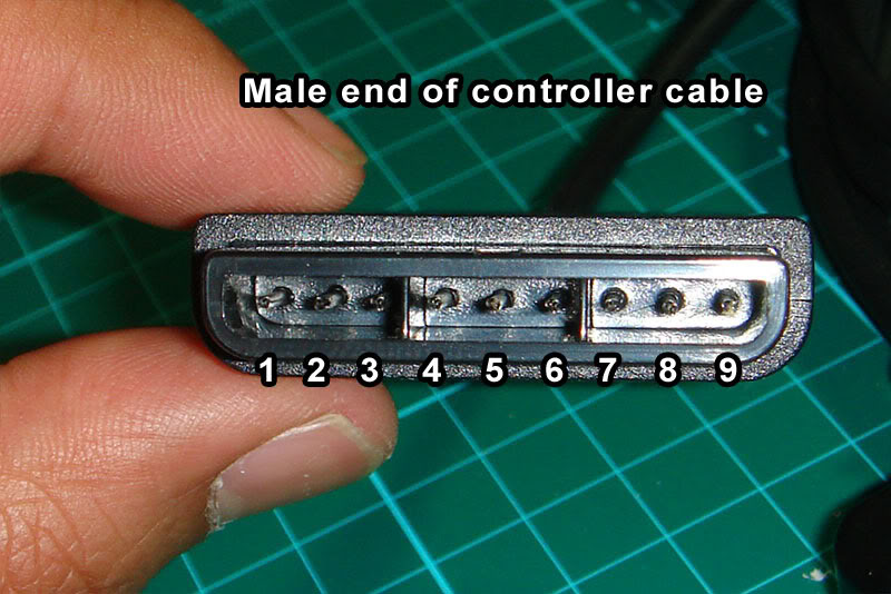
PSX is another good one, since it covers both PS1 and PS2 and was considered the "standard" connector for sticks prior to the adoption of USB, so you can find PSX-to-whatever adapters fairly easily from companies like Raphnet. In fact, Akishop Customs recommends using a PSX cable with a PSX-to-Gamecube adapter to cover Gamecube and Wii inputs with PS360+ boards.
Note: the 'RUMBLE' pin carries 7.2v-9v for use by the rumble motors. We don't need to mess with it.


PSX Pin - Purpose - RJ45 Pin - Cthulhu - ETH Color
1 DATA - 4 - C - Blue Solid
2 CMD - 3 - B - Green Stripe
3 RUMBLE - --- - ---
4 GND - 1 - G - Orange Stripe
5 +3.3v - 8 - V - Brown Solid
6 ATTN - 5 - D - Blue Stripe
7 CLK - 2 - A - Orange Solid
8 UNUSED - --- - ---
9 ACK - 7 - F - Brown Stripe
and here's that same data shuffled around to use the order of the RJ45/Cthulhu pins, in case that is easier to understand:
PSX Pin - Purpose - RJ45 Pin - Cthulhu - ETH Color
4 - GND - 1 - G - Orange Stripe
7 - CLK - 2 - A - Orange Solid
2 - CMD - 3 - B - Green Stripe
1 - DATA - 4 - C - Blue Solid
6 - ATTN - 5 - D - Blue Stripe
--- - --- - 6 - E - Green Solid
9 - ACK - 7 - F - Brown Stripe
5 - +3.3v - 8 - V - Brown Solid
NES and SNES
SNES / NES is another interesting case insofar as they use the same protocol, just with a different connector. Rather than making/storing/transporting 2 separate ethernet cables, I made one ethernet-to-SNES cable and use a self-made SNES-to-NES adapter for NES (also useful for using the more ergonomic SNES pad on an NES). I also have a cheap SNES-to-Wiimote-expansion adapter (this one from Hyperkin https://www.amazon.com/Hyperkin-Controller-Adapter-Classic-super-nintendo/dp/B075RMYMNH) but neither my PS360+ nor my MC-Cthulhu work with my SNES Classic/Mini through it, so YMMV (worth noting: MC-Cthulhu and PS360+ don't work with my Analogue Super Nt using the normal SNES cable, either, though they both work with an actual SNES console, so clearly something fucky is going on that probably won't ever be resolved for either of the essentially dead products). I haven't tried either of them running through a Wiimote's Bluetooth connection (to, for example, use an arcade stick wirelessly with emulators on a softmodded Wii), so if you try that, please let me know your results in the comments.
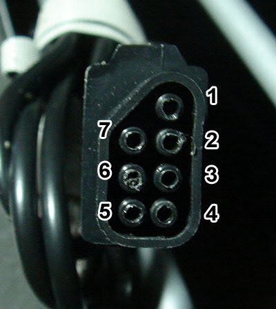
To be verbose, here are both the NES and SNES pinouts and pics, respectively (the "unused" pins are reserved for special controllers and serve no purpose for us):
NES


NES pin - Purpose - RJ45 pin - Cthulhu - ETH Color
1 - GND - 1 - G - Orange Stripe
2 - CLK - 2 - A - Orange Solid
3 - LATCH - 7 - F - Brown Stripe
4 - DATA - 4 - C - Blue Solid
5 - UNUSED - --- - --- - ---
6 - UNUSED - --- - --- - ---
7 - VCC - 8 - V - Brown Solid
And here it is sorted by RJ45 pin:
NES pin - Purpose - RJ45 pin - Cthulhu - ETH Color
1 - GND - 1 - G - Orange Stripe
2 - CLK - 2 - A - Orange Solid
5 - UNUSED - 3 - B - Green Stripe
4 - DATA - 4 - C - Blue Solid
6 - UNUSED - 5 - D - Blue Stripe
--- - --- - 6 - E - Green Solid
3 - LATCH - 7 - F - Brown Stripe
7 - VCC - 8 - V - Brown Solid
SNES


SNES pin - Purpose - RJ45 pin - Cthulhu - ETH Color
1 - GND - 1 - G - Orange Stripe
2 - UNUSED - --- - --- - ---
3 - UNUSED - --- - --- - ---
4 - DATA - 4 - C - Blue Solid
5 - LATCH - 7 - F - Brown Stripe
6 - CLK - 2 - A - Orange Solid
7 - +5v - 8 - V - Brown Solid
And sorted by RJ45 pin:
SNES pin - Purpose - RJ45 pin - Cthulhu - ETH Color
1 - GND - 1 - G - Orange Stripe
6 - CLK - 2 - A - Orange Solid
2 - UNUSED - 3 - B - Green Stripe
4 - DATA - 4 - C - Blue Solid
3 - UNUSED - 5 - D - Blue Stripe
--- - --- - 6 - E - Green Solid
5 - LATCH - 7 - F - Brown Stripe
7 - +5v - 8 - V - Brown Solid
TurboGrafx-16 / PC-Engine
TG16/PCE is kinda weird insofar as it has 2 functions on each pin (e.g. D-pad up and the I button)
and then it uses the DATA SELECT pin
to select which set of functions to poll.
I don't have a TG16/PCE, but from rtdzign:
The American TurboGrafx-16 uses has a female Din 8 port on the system while the Turbo Duo and all the Japanese systems use a Mini Din 8. I recommend that you buy a number of 6 ft monoprice Mini Din 8 cables. For an TG-16 you can buy a male Din 8 connector and solder that to an ethernet cable.

And here's the diagram sorted by DIN pin:
DIN Pin - RJ45 pin - Cthulhu - ETH Color
1 +5v - 8 - V - Brown Solid
2 UP/I - 2 - A - Orange Solid
3 RT/II - 3 - B - Green Stripe
4 DN/Sel - 4 - C - Blue Solid
5 LF/Run - 7 - F - Brown Stripe
6 SELECT - 6 - E - Green Solid
7 OE - 5 - D - Blue Stripe
8 GND - 1 - G - Orange Stripe
And sorted by RJ45 pin:
DIN Pin - RJ45 pin - Cthulhu - ETH Color
8 GND - 1 - G - Orange Stripe
2 UP/I - 2 - A - Orange Solid
3 RT/II - 3 - B - Green Stripe
4 DN/Sel - 4 - C - Blue Solid
7 OE - 5 - D - Blue Stripe
6 SELECT - 6 - E - Green Solid
5 LF/Run - 7 - F - Brown Stripe
1 +5v - 8 - V - Brown Solid
Saturn
Saturn pads have voltage lines running in and out of the gamepad. When you see diagrams online, they are typically named according to the console's perspective, rather than the controller's, so keep in mind that these names are basically backward.

Sorted by Saturn pin:
Sat Pin - RJ45 pin - Cthulhu - ETH Color
1 +5v-OUT - 8 - V - Brown Solid
2 DATA1 - 3 - B - Green Stripe
3 DATA0 - 2 - A - Orange Solid
4 SELECT0 - 5 - D - Blue Stripe
5 SELECT1 - 6 - E - Green Solid
6 +5v-IN - --- - --- - ---
7 DATA3 - 7 - F - Brown Stripe
8 DATA2 - 4 - C - Blue Solid
9 GND - 1 - G - Orange Stripe
Sorted by RJ45 pin:
Sat Pin - RJ45 pin - Cthulhu - ETH Color
9 GND - 1 - G - Orange Stripe
3 DATA0 - 2 - A - Orange Solid
2 DATA1 - 3 - B - Green Stripe
8 DATA2 - 4 - C - Blue Solid
4 SELECT0 - 5 - D - Blue Stripe
5 SELECT1 - 6 - E - Green Solid
7 DATA3 - 7 - F - Brown Stripe
1 +5v-OUT - 8 - V - Brown Solid
3DO
3DO pads have headphone jacks on them, so 2 of the pins are dedicated to carrying audio signals, and there's a second VCC line. I would assume you can use either of them but haven't tested it, since I don't have a 3DO. Neither did rtdzign, it seems, as here's what he had to say about it:
(I don't have a 3DO and am assuming the D-sub follows normal pinout convention Picture is from a 3rd party genesis extension cable.)
3do will currently only work as the only controller, plugged directly into the system; trying to daisy chain off of it or use it through a daisy chain isn't going to work.

Here's the diagram sorted by Dsub pin:
Dsub Pin - Purpose - RJ45 pin - Cthulhu - ETH Color
1 - GND - 1 - G - Orange Stripe
2 - VCC+5v - 8 - V - Brown Solid
3 - AUDIO1 - --- - ---
4 - AUDIO2 - --- - ---
5 - VCC+5v - --- - ---
6 - P/S - 7 - F - Brown Stripe
7 - CLOCK - 2 - A - Orange Solid
8 - GND - --- - ---
9 - DATA - 4 - C - Blue Solid
And sorted by RJ45:
Dsub Pin - Purpose - RJ45 pin - Cthulhu - ETH Color
1 - GND - 1 - G - Orange Stripe
7 - CLOCK - 2 - A - Orange Solid
--- - --- - 3 - B - Green Stripe
9 - DATA - 4 - C - Blue Solid
--- - --- - 5 - D - Blue Stripe
--- - --- - 6 - E - Green Solid
6 - P/S - 7 - F - Brown Stripe
2 - VCC+5v - 8 - V - Brown Solid
Dreamcast
No VMU support and only works with games that can be played solely with an arcade stick. (update 8/4/23): Someone in the comments reported that the original pic was wrong, so here's a corrected pic:
The diagram was always correct:
Here's the diagram sorted by DC pin:
DC Pin - RJ45 Pin - Cthulhu - ETH Color
1 DATA1 - 7 - F - Brown Stripe
2 VCC+5v - 8 - V - Brown Solid
3 GND - 1 - G - Orange Stripe
4 SENSE - 3 - B - Green Stripe
5 DATA5 - 4 - C - Blue Solid
And sorted by RJ45 pin:
DC Pin - RJ45 Pin - Cthulhu - ETH Color
3 GND - 1 - G - Orange Stripe
--- - 2 - A - Orange Solid
4 SENSE - 3 - B - Green Stripe
5 DATA5 - 4 - C - Blue Solid
--- - 5 - D - Blue Stripe
--- - 6 - E - Green Solid
1 DATA1 - 7 - F - Brown Stripe
2 VCC+5v - 8 - V - Brown Solid
Sega Genesis / Mega Drive
None of these boards work with Genesis / MD because it does its own crazy thing that's very difficult to reproduce without spending a ton of money on dedicated parts. The best thing to do for these is to padhack a crappy 6-button pad, which can be purchased online for peanuts.
See my post here for a look at that process.
MC-Cthulhu Secondary Solder Point Pinout
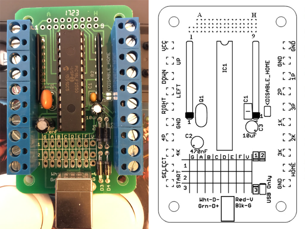
The Cthulhu boards include a double-row of unlabeled solder points on the side of the board opposite the RJ45 solder points. These are intended for attaching a 360 padhack for adding 360 support, but they're just additional hard-lines tied to the screw-terminals, so they can technically be used to add any additional PCB, so long as you tie the VCC and Grounds together.
Since they're unlabeled, it can be a hassle to use them, but you can easily identify by testing continuity between the solder points and the screw-terms. Nevertheless, I'll include the pinout here to make it easier (the labeling scheme assumes right-alignment; that is, H and 9 are on the far right, lined up, while A and 1 are staggered on the left side):
[A] [B] [C] [D] [E] [F] [G] [H]
[1] [2] [3] [4] [5] [6] [7] [8] [9]
A = VCC
B = Down
C = Ground
D = Select
E = Right
F = 3K ('Roundhouse' in Street Fighter nomenclature)
G = 3P (Fierce)
H = 1P (Jab)
1 = Up
2 = 4P (PPP)
3 = Left
4 = 4K (KKK)
5 = Start
6 = 2K (Forward)
7 = 1K (Short)
8 = 2P (Strong)
9 = Home/Guide
And, just because I keep needing it and don't feel like searching for it every time, here's a copy of the MC-Cthulhu pinout: