Showing posts with label retro. Show all posts

Monday, October 14, 2019

Adding Genesis/MD to MC-Cthulhu

So, about a year ago I had been working on a plan for a universal arcade stick with support for a bunch of retro consoles plus PC and PS3 (via an MC-Cthulhu board), Sega Genesis / Mega Drive via a padhacked 6-button pad from eBay and Xbox 360 via a leftover control board from one of my Mad Catz sticks.

360 and Cthulhu were supposed to share the same USB-over-RJ45 with a toggle switch to go between them and Genesis/MD was going to have a little pigtail that could hook up to an extension cable when needed. When I got the 360 board wired into the Cthulhu, though, everything went haywire with phantom button presses and all sorts of nonsense. This got me pretty bummed out about the whole project and I put it on ice.

However, there's been a lot of interest over on my MC-Cthulhu pinout page from people trying to integrate Genesis/MD input with the Cthulhu board since then, so I figured I'd better at least finish up that part and report my experience, which I finally did last night.

I won't go into a ton of detail in this post, as the "how" bits have already been covered in my other posts (linked above), so instead I'll focus on what worked and what didn't.

First off, I had originally tried swapping between the Cthulhu and the 360 board (before I abandoned it) using a momentary DPDT switch like you find on a guitar foot pedal. I wanted something tough that was hard to press, so it wouldn't trigger accidentally mid-game. This ended up being the wrong tool for the job, though, as it only switched to the other board while the switch was actually held down. So, I switched over to an ON/ON DPDT 2-position switch. I'm pretty confident this would have worked as intended had my 360 board wanted to cooperate.

The way the switch is supposed to work is: from your USB, you have 4 lines--GND, 5v, Data+ and Data-. The 5v and GND are wired onto the extra solder points on the Cthulhu (that is, the 3 sets of thru-holes where you solder on the RJ45 lines) and the Data+/- lines are wired onto the switch, with 2 coming from the Cthulhu and 2 coming the 360 board's USB header. The output lines from the switch (typically the 2 center leads) connect to the RJ45 lines. In normal use, both boards will be powered (whenever you do a multi-board solution, all boards need their voltage and ground lines connected together at all times) but the one that actually sends/receives data will be controlled by the toggle switch.

Once I got the boards wired together and noticed the strange behavior, I did a lot of troubleshooting and determined that just having the 5v and GND lines linked up was enough to break everything, so that was that. I may revisit it another time with a different 360 board, but for now I decided to just drop 360 support altogether. With the 360 board out of the picture, I didn't need the switch anymore, but I just left it on there anyway rather than having a gaping hole in the side of my stick for dust and liquids to sneak in. Plus, now I have a little fidget thingie I can fiddle with between matches.

sorry for blurry pic :(

Moving on to the Genesis/MD pad, there wasn't really anything unexpected. I soldered the padhack's button lines to the secondary soldering points on the Cthulhu (the 2 rows of thru-holes labeled A-H and 1-9) as outlined at the end of my pinout post and it all works great. The crummy pad I used has a very short cable, which made it super-easy to cram into my already-crowded Mad Catz SE chassis.
Yes, the wiring is a mess. Good thing nobody ever sees it but me (and now you)
You'll notice I did a little loop around a screw post before sending the connector out the back side. That's to prevent the wire from tugging on the pad PCB and ripping out my solder joints. I also covered the entire PCB and solder points with electrical tape to prevent any stray grounding/bridging.
The pigtail. It's pretty unobtrusive without the extension cable attached
You might also notice that I removed the 360 home/LED/turbo panel with a 3D-printed blank, which just barely fits a 24 mm button to serve as the Cthulhu's HOME button.

While I was at it, I took a tip from u/gongfuren on reddit's r/fightsticks board and swapped out some plungers on my short-stem IL competition buttons for a cool "bullseye" look and also removed the springs from the buttons, which gives them a much lighter touch. They're still a lot stiffer than Sanwa buttons (which is good, IMO, as I like to rest my hands on the buttons) but they feel significantly more responsive than with the spring, and they still keep their satisfying cherry click.

Here's the final result:
And here's my other IL stick that I swapped plungers with:

Saturday, December 22, 2018

Retro Console RJ45 Pinouts - PS360+, MC-Cthulhu, Brook Retro Board

I build a lot of arcade sticks and I like to use them on old video game consoles, and the best way to do this is usually to get a control board that is compatible with multiple consoles. There have been a few boards that do this over the years, including Toodles' MC-Cthulhu (mostly discontinued but still available sporadically), Akishop Customs' PS360+ (discontinued) and now (at the time of this writing) Brook's Retro Board.

The preferred way to connect these boards to the consoles is via RJ45 connectors soldered to the board and then a console-specific connector soldered onto the other end of the cable. A few arcade parts stores sell premade cables for some of the more popular consoles at the time of this writing, but that will probably stop at some point, so it's good to know how to put these cables together.

There used to be a huge thread with really great tutorials on making these cables on the Shoryuken forums by user "rtdzign" but when SRK migrated to a different forum software a few years ago, it completely fucked up their post index so you can't get to things from google search results and I think the whole forum is shutting down completely soon, so all of this will be lost (most of it already is, really; I had to go sifting through the Wayback Machine's archives to collect most of this stuff).

Anyway, here goes (note: the pics in this post come from rtdzign's original tutorial on SRK and from Akishop Custom's PS360+ manual, with copyrights for those respective images belonging to them):

If you buy a MC-Cthulhu from somewhere, you may want to make sure you have the latest firmware. Toodles' "Godlike Controls" site has been down for a while, but the Wayback Machine cached the firmware file here.
Mirror

The ethernet connection pinout looks like this:

USB

The first cable you'll probably want to make is a regular USB cable (for PC and PS3). It's pretty simple - ground (pin 4 of the USB cable) goes to pin 1 of the ethernet cable, data+ (USB pin 3) goes to pin 5 of the ethernet cable, data- (USB pin 2) goes to ethernet pin 6 and VCC (USB pin 1) goes to ethernet pin 8.

Color - Purpose - RJ45 Pin - Cthulhu - ETH Color
Black - GND     - 1        - G       - Orange Stripe
---   - ---     - 2        - A       - Orange Solid
---   - ---     - 3        - B       - Green Stripe
---   - ---     - 4        - C       - Blue Solid
White - DATA-   - 5        - D       - Blue Stripe
Green - DATA+   - 6        - E       - Green Solid
---   - ---     - 7        - F       - Brown Stripe
Red   - VCC     - 8        - V       - Brown Solid

Original Xbox

Once you've done USB, OG Xbox is a logical next choice, as it's just USB with a proprietary plug:


OG Xbox also has a yellow wire that is unused and can be ignored, but otherwise it's the same as the regular USB cable.
NOTE: in general, don't trust wire colors blindly. *Always* test continuity with a multimeter to confirm wire-to-pin assignment. Cheap, knockoff extension cables are notorious for using essentially random wire colors (including nonsense like red GNDs, black VCCs, etc.)
If your construction skills aren't great and you would rather buy something, I believe you could also just use a USB-female-to-Xbox-male adapter like this one (or build one) and get the same effect pairing it with your newly constructed RJ45-to-USB cable.

Once you've got the hang of it, the rest of the consoles are just a matter of matching up the gamepad pins with the ethernet wires.

Gamecube

Gamecube (not compatible with PS360+) only uses the first 3 pins of the controller, which makes it pretty easy: controller pin 1 is VCC, which goes to ethernet pin 8, controller pin 3 is GND, which goes to ethernet pin 1 and controller pin 2 is DATA, which goes to ethernet pin 7. Easy-peasy.

Here's the diagram:

GC Pin - Purpose - RJ45 Pin - Cthulhu - ETH Color
1      - +5v     - 8        - V       - Brown Solid
2      - DATA    - 7        - F       - Brown Stripe
3      - Ground  - 1        - G       - Orange Stripe
And the same info in order of RJ45/Cthulhu pins:
GC Pin - Purpose - RJ45 Pin - Cthulhu - ETH Color
3      - Ground  - 1        - G       - Orange Stripe
---    - ---     - 2        - A       - Orange Solid
---    - ---     - 3        - B       - Green Stripe
---    - ---     - 4        - C       - Blue Solid
---    - ---     - 5        - D       - Blue Stripe
---    - ---     - 6        - E       - Green Solid
2      - DATA    - 7        - F       - Brown Stripe
1      - +5v     - 8        - V       - Brown Solid

N64

The Brook Retro Board has support for N64, and its pinout is very similar to the Gamecube's but in reverse order. That is, pin 1 is GND, pin 2 is Data and pin 3 is VCC (+3.3v).

N64 Pin - Purpose - RJ45 Pin - Cthulhu - ETH Color
1       - Ground  - 8        - G       - Orange Stripe
2       - DATA    - 7        - F       - Brown Stripe
3       - +3.3v   - 1        - V       - Brown Solid
And the same info in order of RJ45/Cthulhu pins:
N64 Pin - Purpose - RJ45 Pin - Cthulhu - ETH Color
1       - Ground  - 1        - G       - Orange Stripe
---     - ---     - 2        - A       - Orange Solid
---     - ---     - 3        - B       - Green Stripe
---     - ---     - 4        - C       - Blue Solid
---     - ---     - 5        - D       - Blue Stripe
---     - ---     - 6        - E       - Green Solid
2       - DATA    - 7        - F       - Brown Stripe
3       - +3.3v   - 8        - V       - Brown Solid

PS1 and PS2

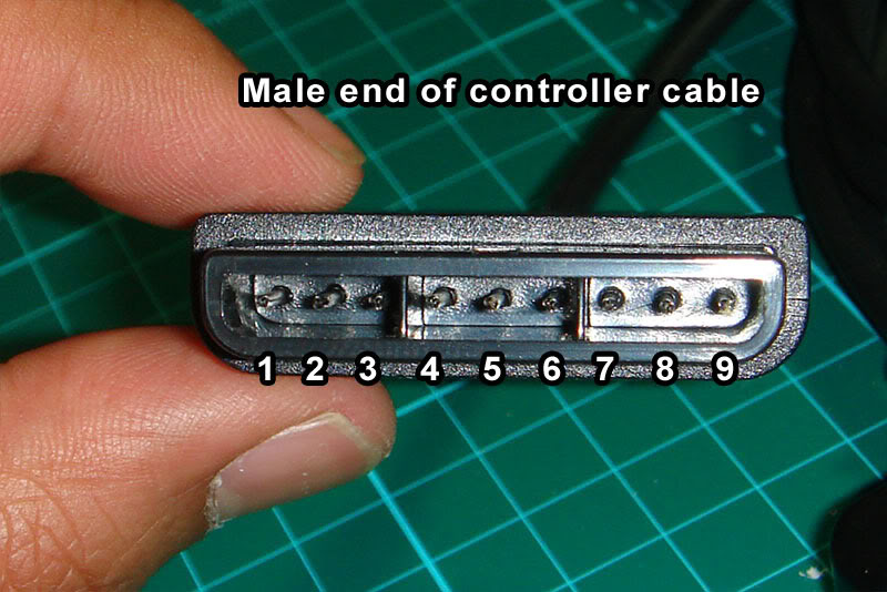
PSX is another good one, since it covers both PS1 and PS2 and was considered the "standard" connector for sticks prior to the adoption of USB, so you can find PSX-to-whatever adapters fairly easily from companies like Raphnet. In fact, Akishop Customs recommends using a PSX cable with a PSX-to-Gamecube adapter to cover Gamecube and Wii inputs with PS360+ boards.

Note: the 'RUMBLE' pin carries 7.2v-9v for use by the rumble motors. We don't need to mess with it.


PSX Pin - Purpose - RJ45 Pin - Cthulhu - ETH Color
1         DATA    - 4        - C       - Blue Solid
2         CMD     - 3        - B       - Green Stripe
3         RUMBLE  - ---      - ---    
4         GND     - 1        - G       - Orange Stripe
5         +3.3v   - 8        - V       - Brown Solid
6         ATTN    - 5        - D       - Blue Stripe
7         CLK     - 2        - A       - Orange Solid
8         UNUSED  - ---      - ---
9         ACK     - 7        - F       - Brown Stripe
and here's that same data shuffled around to use the order of the RJ45/Cthulhu pins, in case that is easier to understand:
PSX Pin - Purpose - RJ45 Pin - Cthulhu - ETH Color
4       - GND     - 1        - G       - Orange Stripe
7       - CLK     - 2        - A       - Orange Solid
2       - CMD     - 3        - B       - Green Stripe
1       - DATA    - 4        - C       - Blue Solid
6       - ATTN    - 5        - D       - Blue Stripe
---     - ---     - 6        - E       - Green Solid
9       - ACK     - 7        - F       - Brown Stripe
5       - +3.3v   - 8        - V       - Brown Solid

NES and SNES

SNES / NES is another interesting case insofar as they use the same protocol, just with a different connector. Rather than making/storing/transporting 2 separate ethernet cables, I made one ethernet-to-SNES cable and use a self-made SNES-to-NES adapter for NES (also useful for using the more ergonomic SNES pad on an NES). I also have a cheap SNES-to-Wiimote-expansion adapter (this one from Hyperkin https://www.amazon.com/Hyperkin-Controller-Adapter-Classic-super-nintendo/dp/B075RMYMNH) but neither my PS360+ nor my MC-Cthulhu work with my SNES Classic/Mini through it, so YMMV (worth noting: MC-Cthulhu and PS360+ don't work with my Analogue Super Nt using the normal SNES cable, either, though they both work with an actual SNES console, so clearly something fucky is going on that probably won't ever be resolved for either of the essentially dead products). I haven't tried either of them running through a Wiimote's Bluetooth connection (to, for example, use an arcade stick wirelessly with emulators on a softmodded Wii), so if you try that, please let me know your results in the comments.

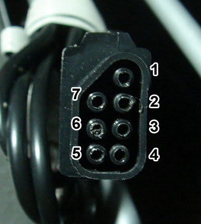
To be verbose, here are both the NES and SNES pinouts and pics, respectively (the "unused" pins are reserved for special controllers and serve no purpose for us):

NES


NES pin - Purpose - RJ45 pin - Cthulhu - ETH Color
1       - GND     - 1        - G       - Orange Stripe
2       - CLK     - 2        - A       - Orange Solid
3       - LATCH   - 7        - F       - Brown Stripe
4       - DATA    - 4        - C       - Blue Solid
5       - UNUSED  - ---      - ---     - ---
6       - UNUSED  - ---      - ---     - ---
7       - VCC     - 8        - V       - Brown Solid
And here it is sorted by RJ45 pin:
NES pin - Purpose - RJ45 pin - Cthulhu - ETH Color
1       - GND     - 1        - G       - Orange Stripe
2       - CLK     - 2        - A       - Orange Solid
5       - UNUSED  - 3        - B       - Green Stripe
4       - DATA    - 4        - C       - Blue Solid
6       - UNUSED  - 5        - D       - Blue Stripe
---     - ---     - 6        - E       - Green Solid
3       - LATCH   - 7        - F       - Brown Stripe
7       - VCC     - 8        - V       - Brown Solid

SNES


SNES pin - Purpose - RJ45 pin - Cthulhu - ETH Color
1        - GND     - 1        - G       - Orange Stripe
2        - UNUSED  - ---      - ---     - ---
3        - UNUSED  - ---      - ---     - ---
4        - DATA    - 4        - C       - Blue Solid
5        - LATCH   - 7        - F       - Brown Stripe
6        - CLK     - 2        - A       - Orange Solid
7        - +5v     - 8        - V       - Brown Solid
And sorted by RJ45 pin:
SNES pin - Purpose - RJ45 pin - Cthulhu - ETH Color
1        - GND     - 1        - G       - Orange Stripe
6        - CLK     - 2        - A       - Orange Solid
2        - UNUSED  - 3        - B       - Green Stripe
4        - DATA    - 4        - C       - Blue Solid
3        - UNUSED  - 5        - D       - Blue Stripe
---      - ---     - 6        - E       - Green Solid
5        - LATCH   - 7        - F       - Brown Stripe
7        - +5v     - 8        - V       - Brown Solid

TurboGrafx-16 / PC-Engine

TG16/PCE is kinda weird insofar as it has 2 functions on each pin (e.g. D-pad up and the I button) and then it uses the DATA SELECT pin to select which set of functions to poll.

I don't have a TG16/PCE, but from rtdzign:
The American TurboGrafx-16 uses has a female Din 8 port on the system while the Turbo Duo and all the Japanese systems use a Mini Din 8. I recommend that you buy a number of 6 ft monoprice Mini Din 8 cables. For an TG-16 you can buy a male Din 8 connector and solder that to an ethernet cable.

And here's the diagram sorted by DIN pin:
DIN Pin  - RJ45 pin - Cthulhu - ETH Color
1 +5v    - 8        - V       - Brown Solid
2 UP/I   - 2        - A       - Orange Solid
3 RT/II  - 3        - B       - Green Stripe
4 DN/Sel - 4        - C       - Blue Solid
5 LF/Run - 7        - F       - Brown Stripe
6 SELECT - 6        - E       - Green Solid
7 OE     - 5        - D       - Blue Stripe
8 GND    - 1        - G       - Orange Stripe
And sorted by RJ45 pin:
DIN Pin  - RJ45 pin - Cthulhu - ETH Color
8 GND    - 1        - G       - Orange Stripe
2 UP/I   - 2        - A       - Orange Solid
3 RT/II  - 3        - B       - Green Stripe
4 DN/Sel - 4        - C       - Blue Solid
7 OE     - 5        - D       - Blue Stripe
6 SELECT - 6        - E       - Green Solid
5 LF/Run - 7        - F       - Brown Stripe
1 +5v    - 8        - V       - Brown Solid

Saturn

Saturn pads have voltage lines running in and out of the gamepad. When you see diagrams online, they are typically named according to the console's perspective, rather than the controller's, so keep in mind that these names are basically backward.

Sorted by Saturn pin:

Sat Pin   - RJ45 pin - Cthulhu - ETH Color
1 +5v-OUT - 8        - V       - Brown Solid
2 DATA1   - 3        - B       - Green Stripe
3 DATA0   - 2        - A       - Orange Solid
4 SELECT0 - 5        - D       - Blue Stripe
5 SELECT1 - 6        - E       - Green Solid
6 +5v-IN  - ---      - ---     - ---
7 DATA3   - 7        - F       - Brown Stripe
8 DATA2   - 4        - C       - Blue Solid
9 GND     - 1        - G       - Orange Stripe
Sorted by RJ45 pin:
Sat Pin   - RJ45 pin - Cthulhu - ETH Color
9 GND     - 1        - G       - Orange Stripe
3 DATA0   - 2        - A       - Orange Solid
2 DATA1   - 3        - B       - Green Stripe
8 DATA2   - 4        - C       - Blue Solid
4 SELECT0 - 5        - D       - Blue Stripe
5 SELECT1 - 6        - E       - Green Solid
7 DATA3   - 7        - F       - Brown Stripe
1 +5v-OUT - 8        - V       - Brown Solid

3DO

3DO pads have headphone jacks on them, so 2 of the pins are dedicated to carrying audio signals, and there's a second VCC line. I would assume you can use either of them but haven't tested it, since I don't have a 3DO. Neither did rtdzign, it seems, as here's what he had to say about it:
(I don't have a 3DO and am assuming the D-sub follows normal pinout convention Picture is from a 3rd party genesis extension cable.)

3do will currently only work as the only controller, plugged directly into the system; trying to daisy chain off of it or use it through a daisy chain isn't going to work.

Here's the diagram sorted by Dsub pin:
Dsub Pin - Purpose - RJ45 pin - Cthulhu - ETH Color
1        - GND     - 1        - G       - Orange Stripe
2        - VCC+5v  - 8        - V       - Brown Solid
3        - AUDIO1  - ---      - ---
4        - AUDIO2  - ---      - ---
5        - VCC+5v  - ---      - ---
6        - P/S     - 7        - F       - Brown Stripe
7        - CLOCK   - 2        - A       - Orange Solid
8        - GND     - ---      - ---
9        - DATA    - 4        - C       - Blue Solid
And sorted by RJ45:
Dsub Pin - Purpose - RJ45 pin - Cthulhu - ETH Color
1        - GND     - 1        - G       - Orange Stripe
7        - CLOCK   - 2        - A       - Orange Solid
---      - ---     - 3        - B       - Green Stripe
9        - DATA    - 4        - C       - Blue Solid
---      - ---     - 5        - D       - Blue Stripe
---      - ---     - 6        - E       - Green Solid
6        - P/S     - 7        - F       - Brown Stripe
2        - VCC+5v  - 8        - V       - Brown Solid

Dreamcast

No VMU support and only works with games that can be played solely with an arcade stick. (update 8/4/23): Someone in the comments reported that the original pic was wrong, so here's a corrected pic:

 The diagram was always correct:

Here's the diagram sorted by DC pin:
DC Pin   - RJ45 Pin - Cthulhu - ETH Color
1 DATA1  - 7        - F       - Brown Stripe
2 VCC+5v - 8        - V       - Brown Solid
3 GND    - 1        - G       - Orange Stripe
4 SENSE  - 3        - B       - Green Stripe
5 DATA5  - 4        - C       - Blue Solid
And sorted by RJ45 pin:
DC Pin   - RJ45 Pin - Cthulhu - ETH Color
3 GND    - 1        - G       - Orange Stripe
---      - 2        - A       - Orange Solid
4 SENSE  - 3        - B       - Green Stripe
5 DATA5  - 4        - C       - Blue Solid
---      - 5        - D       - Blue Stripe
---      - 6        - E       - Green Solid
1 DATA1  - 7        - F       - Brown Stripe
2 VCC+5v - 8        - V       - Brown Solid

Sega Genesis / Mega Drive

None of these boards work with Genesis / MD because it does its own crazy thing that's very difficult to reproduce without spending a ton of money on dedicated parts. The best thing to do for these is to padhack a crappy 6-button pad, which can be purchased online for peanuts. See my post here for a look at that process.

MC-Cthulhu Secondary Solder Point Pinout

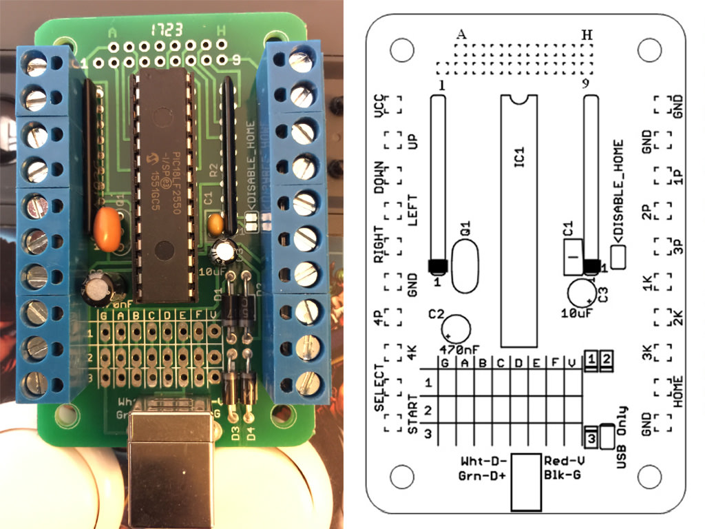
The Cthulhu boards include a double-row of unlabeled solder points on the side of the board opposite the RJ45 solder points. These are intended for attaching a 360 padhack for adding 360 support, but they're just additional hard-lines tied to the screw-terminals, so they can technically be used to add any additional PCB, so long as you tie the VCC and Grounds together.

Since they're unlabeled, it can be a hassle to use them, but you can easily identify by testing continuity between the solder points and the screw-terms. Nevertheless, I'll include the pinout here to make it easier (the labeling scheme assumes right-alignment; that is, H and 9 are on the far right, lined up, while A and 1 are staggered on the left side):

    [A] [B] [C] [D] [E] [F] [G] [H]
[1] [2] [3] [4] [5] [6] [7] [8] [9]

A = VCC
B = Down
C = Ground
D = Select
E = Right
F = 3K ('Roundhouse' in Street Fighter nomenclature)
G = 3P (Fierce)
H = 1P (Jab)

1 = Up
2 = 4P (PPP)
3 = Left
4 = 4K (KKK)
5 = Start
6 = 2K (Forward)
7 = 1K (Short)
8 = 2P (Strong)
9 = Home/Guide

And, just because I keep needing it and don't feel like searching for it every time, here's a copy of the MC-Cthulhu pinout:

Sunday, April 3, 2016

SCART to JP21 Adapter - Solderless DIY

Most of my consoles are setup for RGB output via SCART connection, and SCART cables and converters are much easier to find than ones wired for JP21. However, my XRGB-Mini Framemeister  only takes JP21, so I've searched all over for a low-cost SCART-to-JP21 adapter to no avail. There's one from a store in the UK that costs like $40+international shipping, which is just too expensive, IMO, and a SCART-to-Framemeister-mini-DIN from retro_console_accessories on eBay (the source for the best-quality retro gaming cables anywhere) for ~$30, which is a bit more reasonable but would cause wear-and-tear on the Framemeister's already-finicky mini-DIN port. Neither of these options seemed very attractive to me, so I figured I'd try the DIY route using a cheap Chinese SCART-passthru-breakout-whatever available for <$4 shipped on eBay:
I'm not altogether sure what the intended purpose of these things is but whatever...
They're sealed shut pretty well but the most effective strategy for cracking them open seems to be applying steady pressure on the sides toward the female end (the curved/scalloped part next to the male end is stronger). I used a C-clamp and slowly tightened it until the clamshell halves started buckling and then popped apart. A bench vise would work well, too.

Once you pop it open, you can cut the wires from the breakout jacks, which will clean out some of the rat's nest inside. In my case, all of the wires were black, which... isn't great:
The input/output switch isn't glued in, so you can remove it and save it for another project.
The female side is soldered in and attached pretty tightly, but the male end is actually pretty easy to work with. Each of the spade-type prongs is secured with a little popout leg in the middle. You can squeeze that in with needle-nose pliers and then press the whole prong inward and pull it through from the inside:
Here you can see one of the removed spade-prongs, with the popout locking mechanism.
Once they're all pulled through, you can rearrange them to match the JP21 pinout and push them back through, as per this key (not my pic, but I'm re-hosting it here because the original Tinypic hosting could vanish at any time):
You'll notice the SCART side has one less ground and one more white, unlabeled prong than the JP21 side. I just left that prong out entirely (#12) and everything still seems to work fine.
Once the prongs are all reordered, you can use a small pokey thing to engage the center-locks, no soldering required. I used a cheap dental tool I had laying around to do the job, but those little pointy electrician's tools (the ones that look like dentists' tools with screwdriver handles) should work fine, too. After that, just glue the casing back together and you should be all set.

Tuesday, March 17, 2015

How to Adjust Focus on Sony PVM Monitor

I just scored a Sony PVM 20m2u monitor the other day and found that the picture was extremely sharp at the edges but slightly soft toward the center, which indicates that it was a bit out of focus. There is no focus setting in the service menu (accessible by pressing the degauss and enter buttons on the front, btw), as it is a physical characteristic that must be adjusted by turning a pot inside the monitor guts, just like on an arcade monitor.

With most(?) arcade monitors, the focus pot is located on the flyback transformer, along with the screen pot that controls the voltage to the electron guns. If you remove the outside case of your PVM and look in from the left (there's a big circuit board thing blocking view from the right), you should see the flyback, which is the big black piece of plastic with wires coming out of it that lead to the neckboard:
There are no easily accessible pots to turn on this flyback, but it is connected to a small white board above and behind it, right against the back panel with all of the inputs (which I did not remove), and that board has our focus pot:
The focus pot, viewed from the back of the monitor
You'll want to turn this pot very slightly while the monitor is running until you have a more uniform sharpness all over. It's nice that they moved it off of the flyback, actually, even though it made it a little harder to track down because it can be scary messing with such a high-voltage component while the monitor is running.

UPDATE (03/20/2015): Someone in the comments asked for shots of it running, so here you go (click thumbnails to embiggen):


These are all extreme closeups, since I figured that's what people are mostly interested in. These were taken with my HTC One m7 with a Playstation 2 hooked up over component cables. The first 2 are Dodonpachi Daioujou in TATE (notice the vertical scanlines), followed by a menu shot, Mega Man X Collection and Street Fighter Anniversary Edition.

As you can see, the scanlines are very crisp and "sterile," though not as much as on a 31 kHz CRT monitor (see the pics at the bottom of this post for comparison). For "240p" non-interlaced content, the PVM sits somewhere between that extreme and a regular SD/CGA TV or monitor, where the gaps between scanlines are almost nonexistent in bright areas.

Saturday, March 29, 2014

TVs and Retro Gaming / Emulation

INTRODUCTION

Retro gaming is a hobby of mine and, as I started looking into hooking my retro consoles up to modern displays, I found a bunch of incomplete information and dead links scattered among various enthusiast forums, along with misunderstandings and oft-repeated misinformation. So, after diving down the rabbit hole and exploring a bunch of different options, I decided to post my findings in the hopes of saving others from making any costly, avoidable mistakes.

THE ISSUES

I have a big LCD HDTV with a HTPC connected that I use for watching videos and playing emulated games, and I can use various shaders to achieve an aesthetically satisfying approximation of how my retro games looked on CRT TVs. However, there are a number of reasons to use the real hardware instead of emulation, such as emulation accuracy deficiencies--which can render some games unplayable or unenjoyable--and/or latency concerns.

Sadly, modern displays like my HDTV make retro consoles look like absolute crap and can create/exacerbate latency issues, as they recognize the consoles' double-strike/"240p" signal as 480i(nterlaced)--and rightly so, since standard NTSC signals are always 480i regardless of how they're presented; the 240p standard was not created until decades later and even then it wasn't referring to the signal from retro consoles--and attempt to deinterlace them. This adds at least 1-2 frames (16-32 ms) of latency as the deinterlacer tries to combine 2 sets of fields to create a full picture, and that's before the signal even reaches the TV's upscaling circuit, which then adds even more latency (how much is added by the scaler can vary wildly from display to display).

To avoid this whole mess, we have a couple of options:

DIGITAL VS ANALOG

If you really want to use your big, digital HDTV but want to minimize latency, you'll want to sidestep the deinterlacing/slow-scaling issue by plugging your console into an external line-doubler/scaler. The cadillac in this area is the XRGB-Mini Framemeister, which is a Japanese import and costs an arm and a leg (about $475 at the time of this writing). This sexy lady will take your "240p" input, double the lines to a true progressive signal and then upscale it to an HD resolution that gets piped to your HDTV via HDMI, all essentially laglessly (it adds ~1.5 frames of latency according to Fudoh from the shmups forum). It will even add in a scanline effect, if you want. If, like me, you don't have $500 to piss away on this sort of thing--awesome as it may be--there are some cheap Chinese boxes that can handle the upscaling and deinterlacing (but not the scanline effect) at a slightly lower quality and substantially lower price. This seems like a good compromise to me, though the loss of scanlines is unfortunate. However, if your upscaler has a VGA output (like these) and your HDTV also has a VGA input, you can put a separate scanline generator, like the SLG-3000 or Toodles' T-SLG, in between and get close to the same quality as the XRGB-Mini for much cheaper.

Another consideration, though, is that the XRGB-Mini also accepts RGB/SCART signals (see the 'Analog Signals' section below for more details), while the cheaper models like the one linked above only accept composite and S-video. :(

UPDATE: I actually did purchase an XRGB-Mini recently and it's beautiful. I highly recommend it and think it's well-worth the money for an enthusiast.

It's also worth noting that any of these upscalers will give you an extremely sharp picture, similar to what you get from unfiltered emulation with nearest neighbor scaling (i.e., super-sharp/pointy pixel edges), so this option is ideal for the pixel fetishists out there but may not be desirable to old-schoolers who grew up playing on crappy little CRT TVs.

If you chose to go the digital route, congratulations: you're done! Your upscaler is providing you with the finest picture available. However, you might still want to read the rest of the information here, as some of it may be useful to you anyway, particularly the parts about analog signal quality.

Personally, those digital, super-sharp pixels never looked good to me. I'm a big fan of the way CRT TVs look and how they handle those low-res images, so I am/was forced to purchase an analog CRT. Even on an old analog display, though, we still want to keep our picture as nice as possible, which brings us to our next concern:

ANALOG SIGNALS

As far as analog signals are concerned, the top of the heap is RGB, meaning you get an isolated signal for each color, which provides a crisp, clear picture when they're all combined. Just below that is S-video, which separates the luma signal (brightness information only; produces a black and white picture) from the chroma (color; R, G and B all together) signal so they don't interfere with each other. Far below that we have composite--the familiar yellow RCA jacks--which combines chroma and luma into a single signal where interference between the two (known as chroma/luma "crosstalk") significantly degrades the picture. Slightly below composite(!), we have RF, which takes the signal and encodes it into the same format used in over-the-air broadcasts (and you know how good those tend to look...). You can compare how these signals differ in quality by loading up an emulator with Blargg's NTSC filter, which has presets to emulate RGB, S-video, composite and RF.

MATCHING INPUTS TO SIGNALS

In the USA, high-quality inputs, such as component and S-video, are not commonly found outside of large (24" and up), high-priced televisions, such as Sony's Wega line, so if you have a big house and plenty of room (and a strong back), you'll probably want to go for a real hoss of a TV with plenty of inputs. Sadly, most small CRT TVs have only coaxial/RF and *maybe* composite/RCA, which means your picture will always look pretty crummy. I lucked out and found an Apex 14" model with an integrated DVD player that also has S-video, which is good enough quality for me, so my retro consoles are now covered.

If--like me--you are satisfied with the quality of S-video and will only be hooking retro consoles up to your analog CRT, congratulations: you're done! If, however, you are a super-picky "videophile" and you think S-video is only fit for unwashed plebs and/or you want to hook your PC up to your CRT, there's more to consider:

THE MANY FACES OF RGB

Within the RGB family, there are about a million different subsets that each serve their own purpose. For TVs in the USA/NTSC world, we have "component" video (terrible, vague name, btw), which is also referred to by the color space it occupies, YPbPr. For PCs, we have VGA, which uses the familiar--typically blue--15-pin connector. For European/PAL-land TVs, we have 21-pin SCART.

Note: Europeans are lucky enough to have SCART as a standard input for CRT televisions, and many retro consoles--SNES, for example--can output this standard directly. This is a pure RGB signal and will provide the cleanest, most crisp analog picture around. HOWEVER!!, Japanese SCART (also known as JP-21 pin) and European SCART have a different pinout and, as such, are not compatible, even though they have the same connector. If you want to use a Japanese/NTSC JP-21 pin cable with a European/PAL TV with a Euro-SCART input, you will need a pin converter like this one. The aforementioned XRGB-Mini, as a Japanese device, does not require such a converter.

Aside from SCART, it's generally pretty difficult to get RGB from retro consoles, but it's usually possible if you're determined enough.

Now, even though all of these signals and connectors are technically RGB, they are incompatible with each other due to differing sync methods and signal frequencies, which means you'll need a display that is compatible with the signal and has jacks available. This brings us to:

15 KHZ VS 31 KHZ DISPLAYS

One of the major limiting factors in a CRT is the horizontal scan rate, which is the frequency at which a display can move the electron gun from the left side of the display to the right and back again. CRT monitors, like the kind you would find attached to a crummy old Packard Bell computer, have a high horiz. scan rate of 31 kHz, while NTSC TVs have a comparatively low scan rate of 15 kHz. Furthermore, devices that expect the high scan rate of 31 kHz displays and send a high-resolution signal are not compatible with--and can actually damage--displays with the lower scan rate if connected. On the other hand, 31 kHz monitors can be coaxed into displaying a "240p" signal using driver hacks like CRT_EmuDriver or xrandr and/or custom xorg.conf modelines (for some excellent info on getting 240p in Windows, see Monroe88's comments after the post). This will produce the highest-quality image possible with an emulator:


The drawback to this setup is that each system you want to emulate needs to render in exactly its native resolution or else it looks like shit, with misshapen pixels and inconsistent scrolling everywhere. The specialized Groovy Arcade distro automates some of this, but you may still have to use your monitor's hardware calibration controls to get the image to fit/center properly. I found the constant tweaking to be a tremendous pain in my ass and not really worth it.

If you're in linux, here's how you can force your monitor to act like an NTSC TV (type into a terminal from an X-session desktop):
xrandr -q
This will tell you which display you're using and which modes are available by default. My display was hooked up to DVI-0 via a DVI-to-VGA adapter.
xrandr --newmode "240p" 5.979 320 332 368 380 240 242 246 263 +CSync
xrandr --addmode DVI-0 240p
(replace DVI-0 with whatever your card reports)
xrandr --output DVI-0 --mode 240p
Some older video cards (like my Radeon X600 pictured below) for PCs will have an S-video output next to their conventional VGA and/or DVI outputs, which allows them to connect directly to a standard 15 kHz TV with S-video input:

This is very convenient, but it comes at a price: the card presents an 800x600 resolution to the PC and then crunches that down to 480i (that is, a standard NTSC signal), and it *cannot* be convinced to do anything else under any circumstances (AFAIK). This output looks pretty good, but it's not nearly as crisp as the VGA 240p 31 kHz image, obviously:
On the other hand, it is only slightly worse than a direct S-video connection from console to 15 kHz TV:
While S-video will always be slightly blurrier than RGB, the 15 kHz display is simply not capable of producing an image as high-quality as the 31 kHz display's due to its lower resolution and larger, chunkier phosphors. If you have a TV with component/YPbPr jacks, you can use a VGA-to-component transcoder box--like this one--to keep a clean RGB signal from your PC to the TV. Since it's a 'transcoder,' you shouldn't suffer any signal degradation, ideally.

UPDATE (11/14/14): Here's a pic of a PC hooked up to a 15 kHz display (an arcade monitor, to be specific) via RGB:
The photo kinda sucks and doesn't really do it justice, but you can see that the space between scanlines is much less pronounced vs the 31 kHz monitor. There's also no NTSC color changes like you see in the S-Video shots, for better or for worse. Anyway, back to the original post...

Sometimes you want to use your actual retro consoles rather than emulating on a PC--particularly in cases where emulation quality is still relatively poor, such as Sega Saturn or Dreamcast--but you still want to get the highest quality possible, which brings us to:

BROADCAST MONITORS

Broadcast monitors are high-resolution CRTs that were used by video professionals, such as broadcasters and video editors, to preview high-quality signals during the production process. They cost thousands of dollars new but are now cheap as dirt (relatively), since those professions have moved on to digital/HD signals and formats. Sony's PVM and BVM series of monitors are the most well-known and sought-after among retro gamers and, as such, often command a higher price than some similar products from other manufacturers. Nevertheless, the *VMs and other similar broadcast monitors tend to come with a variety of high-quality inputs, including one or more RGB equivalents (though often with separate sync, which can require conversion from, say, SCART). Another nice thing about these monitors is that they tend to come with nice, flat sides, unlike most TVs, which allows them to be rolled onto their sides easily for TATE mode games, like shooters.

Broadcast monitors are available in sizes up to 30" or so, though models that large are extremely hard to find and tend to be quite expensive, even now, due to their rarity. They are also very expensive to ship, due to their weight, which means many of the auctions on eBay are local-pickup-only (and tend to be in California...). The smaller models of 20" or less are much more common, and can usually be had for between $200 and $300 dollars at the time of this writing. A direct RGB connection from a console to one of these monitors should produce a picture as glorious as the aforementioned PC-VGA-to-240p-31-kHz setup, only without the hassles of modelines, hacked drivers, etc. Unfortunately, I don't have such a monitor, so I can't share any pictures :(

In the cases of either the 31 kHz or broadcast monitors, I personally find the image to be a bit sterile and actually prefer the 15 kHz option. I have opted to use the S-video-out on my video card for the convenience it provides, and the quality degradation is only about as bad as choosing bilinear vs nearest neighbor scaling in an emulator (i.e., fine for me, unbearable for perfectionists and pixel-lovers).

UPDATE (4/13/2015): I recently picked up a PVM 20M2U 20" monitor and posted some closeup shots on this page. The picture is indeed awesome and actually sits somewhere between regular SD/CGA displays and high-res 31 kHz monitors in "sterility" and how crisp the scanlines render.

Anyway, here are some more PC-VGA-to-240p-31-kHz pics :D


Good detail shot of the scanlines and the black gaps visible between.
This is what happens to SNES pseudo-hires transparency (bsnes) for some reason :/


Some other considerations that I will add to this post soon: CRTs for 480p and higher consoles (PS2, Dreamcast, 360, etc.), 31 kHz at 1024x768 (shaders vs the real thing), I plan to add a decision-making flowchart with approximate costs at some point, as well.

Analytics Tracking Footer