Showing posts with label DIY. Show all posts

Monday, December 12, 2022

How to DIY Universal TRS MIDI Adapter

 MIDI is great. It's been around forever and lets all of our synths communicate with a simple protocol across a sturdy and robust 5-pin DIN connector. Unfortunately, as devices have gotten smaller and space on those devices becomes ever more valuable, many manufacturers have ditched the venerable 5-pin DIN connectors for the smaller (and cheaper) MIDI-over-TRS (TRS stands for Tip/Ring/Sleeve; it's known informally as 3.5mm stereo or "aux" cable). When I first learned of this shift, I didn't think much about it. My device came with a TRS-to-female-DIN adapter and that was that.

Until I got a second TRS-MIDI device and none of my dongles worked with it.

I'm not sure on the history of how this came to be, but there are actually two competing and physically incompatible MIDI-over-TRS standards, known as "type A" and "type B". Some manufacturers tend to use type A connections while others use type B. As far as I've seen, this information--that is, which standard any given device uses--is never printed beside the ports on the device, and it's very rarely on the adapter dongles (I've only ever seen it labeled on third-party adapters, never first-party).

Both standards use the same pins from a 5-pin DIN--the 2, 4 and 5 pins, to be exact--and both use pin 2 (the one at the bottom/middle) as the ground pin:

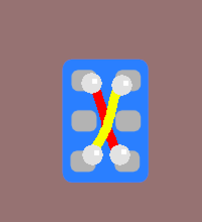
The only difference between the two standards is whether pin 4 is Rx and pin 5 is Tx or vice versa. Infuriatingly similar.

After buying and selling some synths, I've ended up with all of my devices using the same standard (I can never remember which) and not enough of the right kind of adapter to cover both input and output on all of them. I considered cutting up some of my adapters from the other standard to swap the polarity (i.e., to convert them to the standard my current gear uses), but I didn't want to keep dealing with this problem in the future, so I decided instead to use a DPDT switch I had lying around to make a universal, switchable TRS-MIDI Type A+B cable.

The first step in this process was to cut open my extra TRS-MIDI cable. You could also accomplish this by cutting up a cheap MIDI splitter cable and a spare TRS/3.5mm/aux cable, which would let you make two universal cables at the same time (to cover both your MIDI in and MIDI out). My cable has a green wire, a white wire and a shield around them, which connects to the ground pin.

So, the way a simple 2-way DPDT switch works is you have 2 pins in the middle and when the switch is turned one way, they bridge to the 2 pins on one side and when you flip the switch the other way, they bridge to the other pins, like so:

Now, looking at the underside of our DPDT switch:

we need to do a criss-cross bridge with some tiny jumper wires to connect our outside pins from one side of the switch with the opposite pins on the other side of the switch, like this:

Next, we solder one side of our cable's wires to the outside legs on one side of the switch, like this (it doesn't matter whether you do the TRS side or the DIN side of the cable; either works):

After that, we take the other side of our cable--whichever one you didn't use in the previous step--and solder its wires to the two inside pins, like this:

Once that's done, the last step is to connect your ground lines together. They're not involved in the switching process at all, so just link 'em up:

That's it. You're done.

I don't know why this problem even exists, and I don't know why nobody makes/sells switchable cables like this, but thankfully, we can deal with it ourselves with little fuss/investment.

Friday, June 11, 2021

MT32-Pi (or MiniDexed) - The best cheap synth value around

Like pretty much everyone else, I decided to get into synths during the COVID lockdown period, but seeing as I'm a cheap bastard, I wasn't too excited about dropping $300+ on each piece of gear and started looking for cheaper ways to explore the hobby. I figured there was sure to be some mostly turnkey, DIY solution based on an Arduino or Raspberry Pi that would give me a quick, low-latency, headless and flexible (and good sounding!) MIDI-controllable synthesizer that I could just flash onto an SD card and be off to the races.

It turns out that this is much more difficult to find than one would expect.

Almost everything I could find is limited and/or poor-quality (everything Arduino-based) or unusably latent and/or extremely difficult to use and set up (everything RPi-based with JACK). RPis also have pretty crummy audio quality from their built-in 3.5mm headphone jack, but that's a minor gripe vs getting it to work at all.

However, I had the astonishing stroke of luck to come across a wonderful, free, open-source project that was just maturing to the point of usability when I was looking, and it checks all of my 'required' boxes and more: mt32-pi.

EDIT (5/30/2022): For the past few months, I've been using another excellent and new (at the time of this writing) software called MiniDexed, which also fills this same niche, but is based on the legendary Yamaha DX7 FM synth. Check it out!

This project describes itself as "a baremetal kernel that turns your Raspberry Pi 3 or later into a Roland MT-32 emulator and SoundFont synthesizer based on Circle, Munt and FluidSynth." For those who aren't familiar with the MT-32, it was a sound generator for MIDI keyboards back in the '80s-'90s but also found success as an ultra-high-end solution for video game audio in the days before CD-ROM soundtracks took over. For a taste of how much better the MT-32 sounded than competing sound solutions, check out this video.

So, just using the built-in MT-32 instruments, you can get some really great, authentic retro sounds, from synth bass to horns to percussion. Mt32-pi also supports SoundFonts, though, through its FluidSynth mode, which really opens up your possibilities to basically anything you could ever want. And, since it runs baremetal, there's no OS running in the background, no ALSA adding latency, no hassle of setting up a JACK server and wondering why your sound doesn't work, etc. It boots up in just a few seconds (it takes about the same amount of time as my pedalboard) and responds with live-performance-friendly low latency.

It seems most of the buzz surrounding this project comes from its usefulness as an outboard sound processor for the (fantastic) MiSTer FPGA retrogaming platform, which doesn't have the resources to do good MT-32 emulation on its own while also emulating the original PC 486 hardware needed to the play the games in the first place. For this reason, if you just go searching around, you'll likely find that most of the information and accessories (there are a number of places selling cases and hats, etc.) are catering specifically to this purpose/market rather than music/performance, but the mt32-pi project's wiki includes plenty of information to track down or build your own, should you feel the need. (as an aside, the mt32-pi developer, d0pefish, didn't even realize there was a demand for the retrogaming aspects of the project, as he created it purely for music/performance purposes, just as it was with the original MT-32)

In my case, I felt the bare minimum was a cheap OLED display (SH1106 and SSD1306 models are both great, simple and compatible options available for $2-$8 on eBay/Amazon/AliExpress) and a couple of arcade buttons to control the mode (MT-32 vs FluidSynth) and to cycle through the available SoundFonts (loadable from a hot-swappable USB drive). I also use an I2S DAC for better sound quality (again, $2-$8 from eBay/Amazon/AliExpress), but you can get by with the built-in if you don't mind occasional crackling in quiet parts. All of this is connected directly to the RPi's GPIO pins via dupont connectors.

I also found the gain to be a bit too low vs my other equipment, so I pair it with a cheap headphone amplifier I built to give it a little more grunt (the popular KKmoon kit is good for this, but I went for the 47 HIFI NE5532 kit instead, as it has more robust thru-hole soldered I/O jacks, which will stand up to repeat plugging/unplugging better than the KKmoon's fragile surface-soldered pads). You can't really see it in the pic as it sits directly underneath the RPi and is almost exactly the same dimensions.

Many of the available hats include full-size MIDI DIN connectors, but you can also use any standard USB-MIDI interface/breakout. In fact, I control mine through an Arturia KeyStep (which is an incredible value in its own right) plugged directly into the RPi's USB ports. That is, both devices are connected via USB-MIDI, with USB on both ends; no actual MIDI ports involved, which leaves those ports free on my KeyStep to control other things, like my Roland TR-08 drum machine. I do get some occasional weird behavior (some stuck/dropped notes) with this setup, though, which I think is caused by the KeyStep pulling too much voltage.


So, between the KeyStep and the RPi plus accessories, my full kit costs somewhere between $150 and $200, with the vast majority of it coming from the KeyStep. This is in-line with Korg's Volca line of products (which are great!), but with more power/flexibility in some ways (the KeyStep has an amazing arpeggiator and powerful sequencer and it can serve as the timing heart of your entire setup, while the Volcas' sequencers are simplistic and lack arps entirely) though admittedly less in others (i.e., no knobs to sculpt your sound on the fly; however, the staggering number of SoundFonts available means the Volca FM's compatibility with DX7 patches makes it the only cheap synth with comparable breadth of sonic possibilities). If you already have a MIDI-capable keyboard/controller lying around, you can get the whole thing going for sub-$50, which is simply impossible to beat, value-wise, and if you're already an RPi enthusiast, you may have everything lying around on your workbench already.

Saturday, October 3, 2020

Building a Cheapo Hitbox-style Stickless Arcade Stick

I've been playing Street Fighter games for nearly 30 yrs (at the time of this writing), so you'd think even complex maneuvers would be long since committed to muscle memory. Instead, I frequently biff even basic moves and I find my piss-poor execution to be a significant impediment to my proficiency.

So, I decided to try out a "Hitbox"-style interface. Also known as a "stickless arcade stick", among other snappy names (for brevity, I'm just going to call them the generic "hitbox"), it's basically just a normal arcade control panel but instead of using the familiar joystick for directional inputs, it uses 4 buttons, one for each cardinal direction. These interfaces became popular a few years ago, as they make certain types of tricky inputs (for example, advanced movement tricks from many games, including "instant air-dashing", so-called "Korean backdashing" and more) essentially trivial to perform. As a Zangief-main, I was intrigued by the possibilities for consistent SPDs, as well as the opportunity to break a lot of bad joystick-handling habits I've developed over the years.

My first hitbox was just thrown together using a spare control panel I was experimenting with and some extra 30mm Sanwa OBSF buttons I had lying around. It works well enough, but most hitbox practitioners prefer using all 24mm buttons with one 30mm button in the middle as the 'jump' button that can be pressed with either thumb. These buttons are usually about $4+ per, and they're usually paired with a Brook Universal control board, and some people will also add an LED controller board, bringing the grand total to somewhere between $150 and $300.

I didn't feel like paying that much and decided to go cheap while I'm still learning, since I may give up on it at some point anyway (that is, I think it definitely helps with my execution, but at the cost of playing intuitively; it's just feels less natural, spontaneous and fun so far).

I went with a board from the "zero delay" family (since proven to be a misnomer; they add up to about a frame of latency in some cases) by SJ@JX that includes dedicated LED power lines and pre-wired .110 quick-disconnects for just under $20 and some cheap 24mm buttons with integrated LEDs that come in 5 colors (fun!).

Buttons first: similar to the expensive buttons from Gamerfinger, the EG Starts buttons have a mechanical keyboard switch, but this time with an Alps-style switch rather than Cherry-style. Contrary to comments on Amazon, they are not clicky and are instead linear and non-tactile. The comments are correct, though, that they have a much longer travel than Sanwa 24mm buttons, the actuation weight is heavier and the actuation point seems a bit farther down (I don't consider this a bad thing, necessarily, as Sanwas are annoyingly sensitive, in my opinion).

 
The integrated LEDs are not simply white LEDs that are tinted by the colored plastic housing as I had suspected. Instead they shine brightly in the actual color. The only thing to be aware of with them is that the LED +/- posts are connected directly to the 2 large solder pads (visible just above the switch in the image) and can easily be jarred loose by too much force. If this happens, there's not a whole lot that can be done about it, as far as I can tell, because when I tried to reflow the solder, it just sucked up off the pad entirely and wouldn't stick back down to the board, no matter how much flux I used. So just be careful and use a light touch.

Now for the board: it comes with a bunch of pre-terminated molex jumpers with Asian-style button-compatible .110 quick disconnects, though there's another model available for the same price that comes with .187 quick-disconnects for use with American-style buttons/switches. It has 3 different modes of operation: the default PC/PS3 mode, an "Android" mode and an xinput/"360 PC" mode (it specifically does not work with Xbox 360). Only the first mode would map in RetroArch, so that's what I stuck with.

The board comes with some sort of SOCD (simultaneous opposing cardinal directions) cleaning, but I get the feeling it may be inadvertent, as it doesn't really make any sense. Left+right=left and up+down=down. So, you could still do a few SOCD shenanigans, like instant-return-to-charge sonic booms from the P2 side, but nothing crazy and game-breaking. (for the record, ideal SOCD-cleaning is left+right=neutral and up+down=up, IIRC)

Unfortunately, the jumper/wires it comes with are wired in such a way that it is impossible to make the aforementioned buttons light up when you press them. Instead, they are lit all the time, which is fine if that's what you're going for, but if you want them to light on press, you have to cut the lines and splice the black lines with the yellow and vice versa.

 Once that's done, the wires should be connected like this:


In my case, I wanted all of the buttons to light up, but the board is only designed to light up the non-directional buttons, and if you have a light-up joystick, there's a separate power line and 5-pin Sanwa-style joystick interface that you can connect. It does have additional, separate directional input jumper jacks, but they are 2-pin (i.e., just signal and ground; missing the power pin entirely), while all of the jumper wires they provided have the 3-pin molex, so they won't even fit the directional jumper jack. My solution was to use male-to-female breadboard jumper wires to steal power from unused buttons (L3 and R3 in my case) and run a pair of jumper wires from each directional jack. The pins from my breadboard wires fit nicely into the molex holes. I did have to hot-glue them into place, though, to keep them from just falling out if you look at them funny.

That wasn't the end of my problems, though, unfortunately.

Most hitbox layouts cram the 24mm buttons very closely together, I guess to minimize how far your fingers need to move or something? I dunno. But in any event, the vinyl nuts that come with the threaded EG Starts buttons are much too large for the distance between the buttons, so I had to get creative with how I torqued them down.

After all that, everything seems to be working well. I wouldn't really recommend going this route as a serious thing, but if you just want to have some fun and save some money and don't mind getting your hands dirty, it seems to do the trick:

Update (11/17/2020): after using it for a while, the Zero-Delay board is a real problem. The SOCD cleaning is strange and the variable latency on inputs (testing puts it anywhere between just under a frame to more than 2 frames) causes a lot of inconsistency in execution. So, I switched to an Arduino Pro Micro running the fantastic DaemonBite program, which was a night-and-day difference, even for me (and I'm not a stickler for latency stuff).
 
The boards cost between $5 and $10 depending on how many you buy, so it's still a very low-cost option vs a Brook board. I was also able to pull enough juice for the LEDs from the Arduino's 5v line, so it was just a matter of duping that line out in parallel to the voltage input lines of the existing cables. I used the same breadboard-jumper-to-molex trick as before.

Thursday, December 14, 2017

FrankenTurntable and Speaker Upgrades

I've been helping a friend of mine with his stereo recently and it got me energized to do some work on my own. First of all, I decided to finish a long-term project of mine that's been on hold since my daughter was born: assembling a turntable out of myriad spare parts, most of which I already had lying around.
The platter and mechanism came from a frustratingly crappy direct-drive linear-tracking turntable that I rescued from the trash. I bypassed all of the control circuitry and wired the power directly to the motor, so it only turns at 33 1/3 RPMs (i.e., no 45s for me), but it seems to be pretty solid and consistent at that, at least. I'm interested in trying some different platter materials at some point, but I doubt the motor has enough torque to handle anything much heavier than the one it came with.

The tonearm comes from a Technics SL-1950. I bought this one used off of eBay for about $50. I mounted it to some spare blocks of wood I had lying around and purchased some long, skinny nuts and bolts that I used to raise it to the appropriate height for the platter and get it leveled properly. I also used the wood to sandwich some female RCA jacks that I spliced onto the tonearm's own wires so that I could hook it up to my preamp using standard RCA cables (the yellow jack is the ground line).

It sounds really good and, despite looking ghetto af, it has a nice, post-apocalyptic DIY charm that that appeals to me. More importantly, though, this raw setup provides a direct line from the tonearm to the preamp/amplifier without any of the circuitry in the way that can lead to signal degradation in many more user-friendly turntables (like my LP-120 before I modded it for a direct connection, as well).

If you'd like to hear the output, it's the turntable I used to make the recordings for my cartridge comparison post.

Next up, I've been giving my Dared VP-20 tube amp a rest lately and am instead using a Lepai LP-2020TI tripath amplifier I purchased from Parts Express. It seems Lepai is no longer producing the original model, the LP-2020A+, which is a shame since it was so well-loved among audio enthusiasts, but they are making what is essentially a clone using a more easily sourced chipset (it pumps out a few extra watts, too, which is nice). It has the same clean, low-distortion sound as the original (as long as you keep the volume dial below about 11 o'clock, just like the original...) and, as much as I like my tube amp, the Lepai provides a clear accuracy that can be a refreshing change of pace from the folksy warmth of the tubes.

Finally, I overhauled my backloaded horns--which I originally fitted with some cheap but adequate drivers from MCM Electronics--with some really nice Tang-Band full-range drivers. Since the MCM drivers are only good to about 4 kHz, I had them set up on a 3-way crossover with some Bohlender Graebener Neo8 midranges. It sounded good, but I've always heard that full-range drivers running uncrossed sound more "realistic" than 2-/3-way setups.

So, I hooked the Tang-Bands up uncrossed with the ribbon tweeters wired in parallel (the Lepai can push the combined 4-ohm load just fine), and sure enough: they sound a lot brighter and more even than the crossed 3-way setup, likely due to the Tang-Band's hump above 15 kHz combined with the natural lack of sensitivity mismatching.

The Tang-Bands are supposed to be good down to 60 Hz, but they were barely usable down to probably 80-100 Hz or so (I suspect the chambers in my horn boxes just aren't large enough for the rated performance), so I definitely need my 15" subwoofer in the mix now (my old 3-way setup benefited from it, as well, but it wasn't strictly necessary). Likewise, the ribbon tweeters are supposed to be on high-pass filters for safety, but I'm pushing such a light load through them that I'm pretty sure they'll be okay.

Sunday, April 3, 2016

SCART to JP21 Adapter - Solderless DIY

Most of my consoles are setup for RGB output via SCART connection, and SCART cables and converters are much easier to find than ones wired for JP21. However, my XRGB-Mini Framemeister  only takes JP21, so I've searched all over for a low-cost SCART-to-JP21 adapter to no avail. There's one from a store in the UK that costs like $40+international shipping, which is just too expensive, IMO, and a SCART-to-Framemeister-mini-DIN from retro_console_accessories on eBay (the source for the best-quality retro gaming cables anywhere) for ~$30, which is a bit more reasonable but would cause wear-and-tear on the Framemeister's already-finicky mini-DIN port. Neither of these options seemed very attractive to me, so I figured I'd try the DIY route using a cheap Chinese SCART-passthru-breakout-whatever available for <$4 shipped on eBay:
I'm not altogether sure what the intended purpose of these things is but whatever...
They're sealed shut pretty well but the most effective strategy for cracking them open seems to be applying steady pressure on the sides toward the female end (the curved/scalloped part next to the male end is stronger). I used a C-clamp and slowly tightened it until the clamshell halves started buckling and then popped apart. A bench vise would work well, too.

Once you pop it open, you can cut the wires from the breakout jacks, which will clean out some of the rat's nest inside. In my case, all of the wires were black, which... isn't great:
The input/output switch isn't glued in, so you can remove it and save it for another project.
The female side is soldered in and attached pretty tightly, but the male end is actually pretty easy to work with. Each of the spade-type prongs is secured with a little popout leg in the middle. You can squeeze that in with needle-nose pliers and then press the whole prong inward and pull it through from the inside:
Here you can see one of the removed spade-prongs, with the popout locking mechanism.
Once they're all pulled through, you can rearrange them to match the JP21 pinout and push them back through, as per this key (not my pic, but I'm re-hosting it here because the original Tinypic hosting could vanish at any time):
You'll notice the SCART side has one less ground and one more white, unlabeled prong than the JP21 side. I just left that prong out entirely (#12) and everything still seems to work fine.
Once the prongs are all reordered, you can use a small pokey thing to engage the center-locks, no soldering required. I used a cheap dental tool I had laying around to do the job, but those little pointy electrician's tools (the ones that look like dentists' tools with screwdriver handles) should work fine, too. After that, just glue the casing back together and you should be all set.

Sunday, July 31, 2011

My DIY Backloaded Horn

Over the past 6 months or so, I've been researching and ultimately building a pair of backloaded horns. At the time of this writing, I've only actually finished one of them, but I decided to go ahead and make a post about it.

My Phase Technology Teatro 7.5s sound great, but they're pretty weak on the low-end. I've been supplementing with a shitty powered subwoofer scavenged from a boxed 5.1 surround system, but it just doesn't cut it, unfortunately, so I decided to build some speakers that would cover it a little better.

Since getting my upper-mid horns and hearing their clarity and definition, I wanted to go with another horn for the bass, if possible. I've seen a lot of really crazy, gigantic basshorns on the internet and wanted to avoid the size that would be required to reach below 100 Hz with a compression driver--not to mention the batshit crazy prices that large-scale compression drivers go for on eBay and Audiogon--so I decided to look into backloaded horns.

Ideally, a horn should be as long as the wavelength of the lowest frequency you wish to reproduce, with a mouth of approximately that same diameter, thus bass horns have to be gigantic to reach low frequencies. You can cheat a little, though, by placing the horn against the floor and/or wall of your room, which lets you cut the wavelength requirement by half for each surface, as it uses the walls/floor as if they were a part of the horn. Furthermore, backloaded horns are typically folded horns, which lets them squeeze a lot of length into a relatively small package. Finally, by starting with a large cone driver, your required horn length is reduced further still.

I used this 8" driver for the horns, based on their high sensitivity, though these would also be an excellent alternative. If you don't plan to supplement the horns with a tweeter like I intend to do, you might also consider using a full-range driver, like this one, though it is obviously more expensive. This driver is another good option if you want to play at high volumes, due to its high power handling and *huge* cone excursion.

I came up with my own design for the horn itself, based loosely on some designs I found around online. However, most of the designs I found have the mouth of the horn opening into the wall, which I was afraid would deaden the sound, based on how directive my upper mid horns are. So, I tweaked those designs a bit and ended up with something I could construct out of a single sheet of 4'x8' of wood (MDF [medium-density fiberboard] is the best for speakers, but it's heavy, expensive and rough on your tools; particleboard is a good compromise, IMO, insofar as it is very cheap, but with many of the same characteristics as the more expensive MDF; plywood works, too, but it's ugly).

I used 1/2" particleboard, though TBH, 3/4" would probably have been a better choice, both for rigidity and sound isolation. The sides are 2'x4', the back is 1'x4' and everything else is 1'x2' (i.e., the front, the top/bottom and the interior partitions; the last piece is cut in half and glued together at a right angle). I'm not going to go into much detail about the actual construction, since I'm a shitty carpenter and I'm sure you can find better instructions on box-making online than I could ever provide. Anyway...
Glue the pieces together using wood glue, and don't be afraid to really gob it on. You want it to seep into all of those little nooks and crannies in the wood and form a good seal. You can see the excess squeezing out from under the board in this pic:
To be sure that the junctions are all airtight and won't be leaking air into each adjacent chambers, you can follow behind with silicone caulk or "liquid nails" formulated for wood, which is what I used:
If you look closely, you can also see the right-angle brackets I used to reinforce the box structure.
After all of the interior structure is glued solidly into place, you can glue the other side panel to seal the cabinet shut. I used the liquid nails instead of wood glue to seal it, with a bunch of cinder blocks, books, records, etc. piled on top to get a good connection while the goo dries:
One thing to remember before sealing the cabinet: go ahead and thread some speaker wire through because it'll be much easier now than if you wait. If you do forget (like I did, actually), you can tie the wire around something (I used my dog's Kong toy), drop it into the speaker hole and then flip the whole thing around until it pops out the mouth of the horn. This is harder than it sounds, though, because these horns are gigantic and heavy as shit.

Another bit of advice, do your painting *after* your gluing (unlike me), so you don't have to worry about excess glue spilling over onto your fancy paint job.

Most of the projects I've seen online make a big deal about filling any cavities with sand or kitty litter so they don't turn into resonance chambers, but I don't really notice any problems and I did not do it. Of course, YMMV.

Anyway, here's the finished product:
You can see my small upper mid horn perched on top. You can also see the speaker wire dangling out of the mouth of the horn, since I haven't purchased proper binding posts yet (maybe never...).

As far as the sound, the bass response is considerably more potent than I expected. The driver works as a direct radiator (so better quality drivers will make a noticeable difference in sound quality), while the low frequencies bounce around inside and bellow out of the horn's mouth. The horn produces some of the clearest, most defined bass I've ever encountered, though it is definitely lacking above 1 kHz. That in mind, I intend to pair it with either this tweeter or this one.

One last picture of the finished horn, this time from the side:
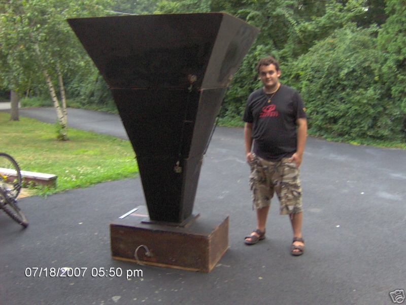
The depth is really what makes these guys huge. Special thanks to my wife, who is gracious and long-suffering :-P

Friday, June 5, 2009

Conclusions and Helpful Links

Continued from Installing the Hardware

That's pretty much it. Just plug it up and give it a shot. If you find that any of your buttons are acting funny, e.g. nothing happens when you press the button until you let go, try swapping the locations of the wires around on the button (i.e., move the wire from the bent post to one of the straight ones and vice versa).

Once again, here's what the final product looks like:


I've presented my own experience here, but there are tons of others' experiences elsewhere online. The Shoryuken.com forums have some really great info on pad hacking and DIY stick-making. You can also find some great things at the arcadecontrols.com forums (HarumaN is an expert and sells pre-hacked pads at reasonable prices) and xbox-scene.com forums (RDC has some great, thorough information about pad hacking, along with some good tutorials on how to salvage pads after a screw-up).

Gamingnow.net sells damn-near anything a stick-builder could want, all at very reasonable prices.

MAMErs can purchase I-PAC interfaces from Ultimarc. Another option that seems to be preferred on the Shoryuken forums is the Cthulhu board, which can be purchased at gamingnow.net.

UPDATE: even better than the Cthulhu is Toodles' new Chimp board, which provides PC/PS3 support and is designed to accept a hacked 360 common ground pad to provide 360 support with automatic switching among protocols. Plus, it's cheaper than bare Cthulhus used to be! You can get it and other stick materials at Lizard Lick.

UPDATE 3/25/11: Even better than the Chimp board, now you can get the Akishop PS360 triple-mod board, which is a no-solder board that supports PS3, Xbox 360 and PC all at once. It costs slightly more (~$45), but it completely removes padhacking from the equation for the first time ever. This and other arcade stick parts intended for fighting game enthusiasts are available at focusattack.com.

If you want to build a standard, semi-low-profile stick similar to what you would buy in a store, I recommend checking out some of the articles on slagcoin.com. The site has TONS of great information about all aspects of stick-making, and their button layout section is unparalleled.

You can learn more about sticks--including the differences between various brands--here. The section about restrictor plates should be considered required reading for any aspiring stick-jockey.

Page 1: Building an Arcade-style Fight Stick
Page 2: Assembling Your Box
Page 3: Pad Hacking
Page 4: Installing the Hardware
Page 5: Conclusions and Helpful Links

Installing the Hardware

Continued from Pad Hacking

After the Hell that is pad hacking, this part is a breeze and is pretty straigtforward. You just put the buttons into the holes you cut in your panel, then screw down the plastic nut to hold them in place. At this point, I wouldn't bother screwing them down too hard because you might need to rearrange/rotate them later.

Next, attach your microswitches to the buttons. This picture shows a standard cherry microswitch that came with my arcade buttons.

When you go to attach the wires from your hacked pad to your microswitches, the best method is to use .187 sized quick releases (or .110 for japanese-style buttons) rather than soldering the wires directly to the posts, which will make repairing/replacing buttons much easier in the future.

For the joystick, you'll need to drill mounting holes around your large-diameter joystick hole. The Happ stick I chose is a top-mounted stick, but I wanted a smooth surface (i.e., no visible screw/bolt heads) so I countersank the holes a bit and then covered the bolts with wood glue and wood putty before staining/sanding.

This is a pretty permanent solution for better or for worse (no way to reposition the mounting bolts), but I intend to continue using Happ sticks in the future, so it shouldn't be too much of a problem.

After the glue and putty dried, I did a light sanding and proceeded to stain the top and sides.

Once that's all set, you can attach your joystick base by threading the mounting bolts through the appropriate mounting holes and then screwing the nuts onto the bolts. Once you have the base of the joystick bolted into place, follow the instructions that came with your joystick for dropping the stalk into place. The instructions for my Happ were not very clear, so I'll explain my process: first, put the plastic ring--textured side-up--on the stalk, followed by the plastic spacer, then push the stalk through the base until it pokes out the other side next to the microswitches. Next, take the actuator (that funky square piece) and PRESS IT DOWN until you can snap the little clip into place to hold it (the fact that it can be pressed down was not mentioned in my instructions and I erroneously thought the spacer was missized).

After that, you just need to attach your pad to the microswitches via the quick releases. The ground attaches to the side post and the signal attaches to one of the two straight posts on the bottom (one side registers when the button is pressed, the other registers until the button is pressed).


Here is how my first attempt ended up (not so hot):


And here's my second attempt (a little better):

At this point, I added a few extra touches, including hinges for the top to maintain easy access to the wiring and some cabinet handles on the back which also double as cable wraps:


Also, as you may have noticed in some of the previous pics, I attached some staples from a staple gun to the bottom of the box interior. I then used cable ties to stabilize the pads against the staples and keep them from flopping around whenever I move the box.


Page 1: Building an Arcade-style Fight Stick
Page 2: Assembling Your Box
Page 3: Pad Hacking
Page 4: Installing the Hardware
Page 5: Conclusions and Helpful Links

Pad Hacking

Continued from Assembling Your Box

If you're not going to use the pad hack method and will instead use an I-PAC or similar control chip, you can skip this part, obviously. For this stage of the construction, I recommend you have an exacto knife, some thinnish wire (~22 AWG; I actually used an IDE hard drive ribbon), a soldering kit (soldering iron and lots of solder, helping hands with a magnifier, a good lamp) and a hot glue gun.

First off, you'll need to remove the outer shell of your controller, usually using a small phillips-head screwdriver.

Once you're down to the bare PCB (printed circuit board), you'll see that all of the button contacts are covered in this weird black coating that solder won't stick to, so we gotta scrape that shit off to get to the sweet, sweet copper underneath it (you'll want to scrape off more than is shown in this picture; it's just an example).

I've heard of people using a dremel with a wire brush attachment to do this, but that sounds like a bad idea to me so I stuck with using an exacto with a square-ish blade (lay it almost flat against the board so you shave off the black stuff instead of scratching it off with the point/edge).

However you decide to do it, just make sure you don't damage the copper underneath because that's what we want to solder to.

Once you get a pair of wires soldered to their corresponding pads, I recommend you plug your controller into your PC/console and bridge the wires (i.e., touch the bare ends together to make a circuit) to verify that the correct button registers. If not, you'll have to figure out what went wrong and redo it. If everything works properly, take out your hot glue gun and encase the whole area in glue to make things sturdier and take the stress off of your solder joints.

Here's a picture of my first attempt, after everything was soldered and glued. I used some cable ties (slightly off-frame up above the pad) to clean up the horrible mess of mess of wires I made:

This is my second attempt, which used IDE ribbon instead of thicker wires. Looks much neater, eh?

After that's all finished, I recommend you attach the wires to a terminal strip or something similar so that you may more easily attach/remove buttons or--god forbid--another pad.

Here are some things regarding pad hacking that were not clearly stated in other sources I read online:
I used the official XBox 360 wired pad from Microsoft (unfortunately, the wireless pads are a total hassle and sometimes break inexplicably during the construction process). Unlike the Mad Catz 360 pad, the official pad does not seem to have a "common ground," which makes things a little harder. The pads with a common ground are set up such that the signal pad of each button can be grounded against the ground pad of almost ANY other button on the PCB. This makes for less soldering and fewer wires to connect to your buttons. In the case of the official pad, you'll need to solder wires to both pads of each button. The silver lining is that you don't need to muck around with any "solder plan" or daisychain any grounds.

So-called "trigger hacking" a.k.a. "set[ting] trigger to neutral" is a pain in the ass, serves no purpose that I can see and has the potential to cause serious problems. It involves desoldering the trigger potentiometers and removing the whole trigger mechanism, then soldering a 10k ohm resister to the leads to make the controller think it's always completely extended. Some people make it sound like this is necessary to even use the triggers, so I did it to my pads and ever since then my button readouts have been very strange (hitting a button doesn't map it to, say, joy1 button 1, but rather to joy1 button 1 joy3 button 1; that is, it thinks the controller is actually 2 controllers at once...). Instead of opening this can of worms, it appears that you could just leave the trigger mechanism and potentiometer intact, hot glue everything in place in the open position (to make sure nothing gets wonky while you're playing) and then solder to the points just like you would with a hacked trigger. Sounds much easier to me. The other option is just to ignore the triggers entirely and deal with the slight hassle of remapping the trigger-assigned button(s) every time you plug the stick into a 360.

Finally, it's easier to make these connections IMO if you place a small drop of solder on the copper pads and then attach the wire to that instead of trying to do it all at once, juggling solder, the PCB and the wire. If you should happen to mess something up, don't freak out; you can follow the lead from wherever you screwed up to the little dot (called a "via") where the lead pokes through to the backside of the PCB. Just scratch away some of the green coating there and you should be able to solder to it (RDC of the xbox-scene forums has a great tutorial for this process).

Page 1: Building an Arcade-style Fight Stick
Page 2: Assembling Your Box
Page 3: Pad Hacking
Page 4: Installing the Hardware
Page 5: Conclusions and Helpful Links

Analytics Tracking Footer