Showing posts with label arcade. Show all posts

Sunday, September 24, 2017

Padhacking a Terrible Genesis 6-button Controller

I recently got a model 1 Sega Genesis and an Everdrive MD and have been playing a lot of the great shmups and arcade ports. The standard 3-button pads are not great, period, but they're especially crummy for those sorts of games (Street Fighter is basically impossible), so I figured I'd seek out some 6-button pads.

Legit 6-button pads from Sega are quite nice, but they're getting more expensive these days (like everything retro, amirite?), so I decided to check out some of the cheap knockoffs. The cheapest ones I could find were going for $8 for 2 pads on eBay and, while I expected them to be shitty, they're worse than I ever imagined:
The Fighting Putt 6B packaging. Both pads I received looked as if they'd been sat upon.
The buttons are so loose I was worried they would fall right out of the cheap plastic casing. The controllers themselves weigh almost nothing and their cord is a measly 3 feet long. The funniest quirk, IMO, is that they only used 4 screws to connect the housing instead of the 5 Sega used, but they put in a fake plastic screw just to keep up appearances:
Very clever, guys. Nobody suspects a thing.
Between the laughably short cord and the awful buttons, I decided to check out the PCB to see if it might be worth putting into an arcade stick (I already have a PS360+ multi-console board, which covers every console I care about except the Genesis/MD, so this would be useful). It turns out that the PCB is actually really great for this purpose, with a common-ground design and nice, big soldering pads for each input:
Here's a shot with wires soldered onto the pads:
And here's one with the solder joints smothered in hot glue for long-term stability:
I hooked it into an existing stick I had lying around and everything works perfectly. After the price of an extension cable, I'm still looking at sub-$10, so not too bad. I wouldn't recommend the Fighting Putt 6Bs for general use, but they're great for padhacking.

Tuesday, August 22, 2017

8bitdo NES30 Arcade Stick Review and Modding Info

I like to play retro games from my couch and I prefer using an arcade stick, but I don't want to have a giant cord stretching across my living room as a tripping hazard. The obvious solution is to get a Bluetooth arcade stick. The only problem: nobody makes them. It seems the people driving the arcade stick market are distrustful of wireless communication due to latency concerns, despite data from a very reputable source suggesting otherwise.

8bitdo had put out a couple of arcade sticks in the past, the FC30 and FC30 Sanwa Edition, but those sticks never got much traction, AFAICT, and they're long-since discontinued now (and I've never seen one come up on eBay). They've revisited the concept recently, though (presumably because their devices are compatible with the Nintendo Switch*, which got a Street Fighter 2 port, and no other company has released an arcade stick for that market), and released their NES30 Arcade stick, which I preordered as soon as I heard about it.

First impressions - Build Quality and Information

The plastic used for the main body of the box feels a little flimsy. It has some flex to it, which isn't encouraging, and there's a lot of empty space inside the stick, though this is actually a good thing when it comes time to start poking around in there. It has a nice, thick, solid metal base with recessed screws and built-in rubber feet, which is a big advantage in my opinion when compared with the flimsy, easily lost rubber feet from the Mad Catz TE and SE sticks (and once the feet were lost, the non-recessed screws would scrape up wooden surfaces and get caught on fabric -_-).

The buttons are knockoff Japanese-style and feel predictably crummy, but passable if you're just going to use it casually. The stick feels pretty decent, really, with none of the gravelly, scraping feelings characteristic of the Mad Catz SE sticks as they slowly ate themselves.

There are 8 full-size (i.e. 30 mm) buttons for A, B, X, Y, R1, L1, R2 and L2 in modern, staggered arcade stick layout, and a smaller button (presumably 24 mm) for Start. There are also smaller non-arcade-style buttons on the control panel for Select, Pair and Turbo. While Select is bindable in gaming software, the Turbo and Pair buttons are not exposed, leaving users with 10 buttons and a 4-way joystick. That is, there is no dedicated "home" button for assigning to "menu_toggle" in RetroArch/MAME.

Wireless connectivity over Bluetooth is quick and painless, and there's no obvious perceptible latency. If you want to play wired and/or charge the stick, 8bitdo has supplied a full-size USB-A-to-A cable, which is, frankly, bizarre. 

Modding

The metal base is held onto the box by 6 small phillips-head screws. Once those are removed, you can pop the base off safely. That is, there is nothing attached to the base that can get yanked out, etc. Once inside, you can see that the wiring is clean and organized, with color-coded wires leading to plastic pin-headers on the board. You can also see the support structure (the hollow tubes surrounding the buttons), which provides a strong backbone where the stick will be seeing the most abuse.
A shot of the insides before I got started on it.
The good news: swapping out the buttons on this stick is a breeze. The stock buttons snap right out and the .110 quick-disconnects transfer over to Sanwa buttons, which are a perfect fit (I swapped in Sanwa 30 mm OBSFS buttons), with no trouble. The stick also has mounting screws that line up perfectly with a Sanwa JLF stick.

The bad news: THIS IS NOT A COMMON-GROUND PCB. That's not a big deal with the buttons (unless you just really like to daisy-chain grounds for tidiness), but it's a very big problem for the stick, since Sanwa and Seimitsu sticks use a common-ground PCB for their switches. In short, this stick is INCOMPATIBLE with Japanese-style sticks without doing some significant modification. Correction: I was totally wrong about this. It is indeed common-ground, and you can just twist up all of the grounds (looking down on the inside of the stick, it's all of the top wires from each signal+ground pair) and attach them to your stick's common ground pin. Dunno what I was doing wrong when I first tried it, but I just now wired up a Seimitsu LS-56 with no issues. So, false alarm.


Speaking of the stick, it has a clip-in square restrictor plate/gate and has the control wires soldered directly to Lema microswitches, from Chinese company Zhejiang Lema Electrics Co. Ltd:
Since they were directly soldered, I needed to cut the wires, making this the first destructive modification so far.

The Lema switches are pretty close in size and shape to the tough-as-nails Cherry microswitches you would find in Happ/IL sticks and buttons, and I decided to swap them out for some I had in an old Happ Competition joystick.
The result is satisfyingly clicky and extremely light (that is, there's barely enough resistance to bring the stick back to center; some people will despise this). I was able to pull off 360/720-degree motions easily and reliably, but I'm not 100% convinced that I want to stick with this setup permanently, so I used insulated alligator clips rather than soldering .187 quick-disconnects to the wires in case I decide to swap it out with other switches in the future.
The extra-roomy case came in handy here for holding my insulated alligator clips
The restrictor plate/gate is held in by 4 little screws and 4 clips. Once the screws are out, the clips are nice and easy to manipulate, unlike the ones on JLF sticks, which are notoriously difficult to work with. I didn't check to see whether Sanwa plates would snap in, but it looks pretty likely. I might swap in an octo-gate at some point and will update this post if I run into any issues. [Update 10/27/2017: by request, I swapped in the Sanwa octo-gate from one of my other sticks and it fit just fine. The Sanwa plate is thicker than the stock plate, so I really had to cram it to get the clips to snap into place, but otherwise, it's no problem.] Here you can see the Cherry microswitches fit in nice and snug under the stock plate:
I didn't get around to testing it, but I suspect the longer, screw-down Happ/IL American-style buttons would fit just fine in the case, since it seems to be a little taller than the Mad Catz SE boxes, which were only about a quarter of an inch too short to fit them comfortably. [Update 10/27/2017: I was wrong, they're almost exactly the same height as the SE box, so the long-stem Happ/IL buttons won't fit, but the short-stem ILs will.]

*Note, the wired vs wireless issue seems to actually be in favor of wireless on the Switch, oddly enough: https://www.youtube.com/watch?v=avvmck40cIw

Wednesday, November 5, 2014

Creating a Custom EDID for Arcade Monitor

Since I got my arcade cabinet up and running with my J-PAC-connected PC running RetroArch, the last finishing touch I wanted was to make it boot directly to the right resolution in a text-mode console and launch RetroArch in KMS mode, which provides the lowest latency and best experience. This ended up being easier than I expected, but it did require some steps I hadn't messed with in the past.

First thing you'll need is a working modeline. I created an ultra-wide 1920x240/60 modeline using this online calculator. Using a wide resolution like this leverages the natural blurriness of CRTs to hide fractional scaling artifacts on the horizontal axis, while the 240 vertical resolution allows perfect 1:1 scaling on the vertical axis. This provides a beautiful, "pixel-perfect" image for a large variety of games, including my favorites--Capcom's CPS-1/2.

This is the resulting modeline (negative sync options added by me):
Modeline "1920x240@60" 31.96 1920 1952 2072 2104 240 245 248 253 -HSync -VSync
I recommend testing your modeline out in a standard desktop environment using xrandr first, since it's pretty low-stakes. If something messes up, you just reboot and everything goes back to normal.

Once you've verified that your modeline works, you're ready to create your custom EDID. There are several good writeups about the process online, but I found this one most helpful. I won't rehash all the steps here, but you essentially just copy the appropriate files from the kernel tree and modify/rename one of the existing EDID source files (I used 1024x768.S) with the values from your modeline (I named mine 1920x240.S).

Here's the important part (i.e., license boilerplate removed for brevity; it's standard GPL2) from mine:
/* EDID */
#define VERSION 1
#define REVISION 3
/* Display */
#define CLOCK 31960 /* kHz */
#define XPIX 1920
#define YPIX 240
#define XY_RATIO XY_RATIO_4_3
#define XBLANK 184
#define YBLANK 13
#define XOFFSET 32
#define XPULSE 120
#define YOFFSET (63+5)
#define YPULSE (63+3)
#define DPI 72
#define VFREQ 60 /* Hz */
#define TIMING_NAME "Ultrawide"
#define ESTABLISHED_TIMING2_BITS 0x08 /* Bit 3 -> 1024x768 @60 Hz */
#define HSYNC_POL 0
#define VSYNC_POL 0
#define CRC 0xf7
#include "edid.S"
Next, compile your source files, which should leave you with 1920x240.bin and 1920x240.bin.ihex (the *.ihex one is unneeded, AFAICT). Open 1920x240.bin with the edid-decode utility (available from the standard Ubuntu repos) and it should tell you something about the checksum being wrong (assuming you're making your own; mine already has the corrected checksum). Reopen your custom *.S and replace the existing, incorrect checksum where it says "#define CRC [whatever]" with the value it says it should have and then re-compile. It shouldn't complain this time.

Here's my compiled 1920x240.bin EDID, which should work for any standard-res 15 khz arcade monitor.

Once you have your shiny new EDID *.bin file, you'll need to create a new directory in /lib/firmware called 'edid,' which will require elevated privileges:
sudo mkdir /lib/firmware/edid
Then copy your *.bin file into it.

Next, you'll need to create a file named drm-kms-helper.conf, which contains only one line:
options drm_kms_helper edid_firmware=edid/1920x240.bin
and move it into your /etc/modprobe.d/ directory (again, needs elevated privs). Of course, you'll need to replace '1920x240.bin' with whatever you've named yours.

At this point, your custom EDID should be usable by your system, so a reboot will get you the desired resolution. If something goes wrong and you need to revert, just delete /etc/modprobe.d/drm-kms-helper.conf and it will put everything back the way it was.

If--like me--you'd like to go all the way and boot to a command line (instead of a standard GUI environment) that uses the new res, you'll want to edit your /etc/default/grub (needs elevated privs again) and replace the line:
GRUB_CMDLINE_LINUX_DEFAULT="quiet splash"
with
GRUB_CMDLINE_LINUX_DEFAULT="text"
Then run 'sudo update-grub' to put it into effect. Now, on subsequent reboots, it won't try to load an X-Server and desktop environment and will instead go straight to console.

Finally, I don't plan on having a keyboard connected to my cabinet all the time (kinda kills the mood, y'know?), so I wanted it to login to my user account automatically. To do this, edit /etc/init/tty1.conf in a text editor and comment out the last line:
#exec /sbin/getty -8 38400 tty1
and add this below it instead:
exec /bin/login -f username < /dev/tty1 > /dev/tty1 2>&1
Replace 'username' with the name of the user account you want to login automatically. And, if you want to have it load a frontend--like RetroArch--as soon as it finishes logging in, you can add the launch command to the end of that user account's ~/.bashrc file.

Monday, November 3, 2014

Neotec 2515c Flyback Transformer Problem

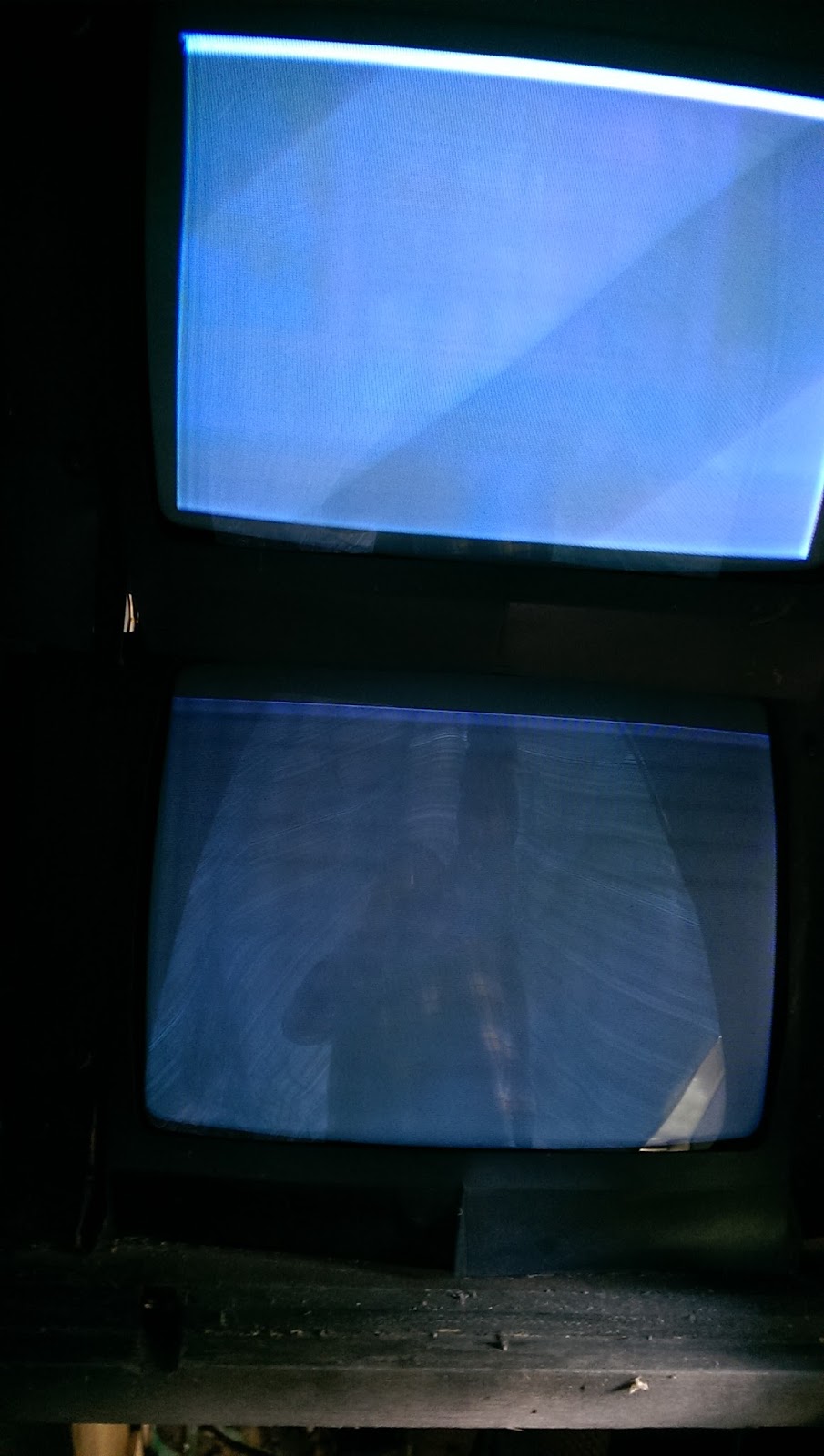
I got my new JAMMA-compatible arcade cabinet up and running with MAME via RetroArch, but I noticed that the screen is blurry and has these weird, diagonal-ish horizontal lines going across the top half of the screen:
After digging around online, it seems these are known as retrace lines, and they occur when the flyback transformer is applying too much voltage to the screen. This behavior is typically accompanied by excessive brightness, as well. Normally, the solution to this would be to find the 'screen' knob on the flyback itself and turn it down just a bit until the lines go away.

However, I also learned that my specific monitor, a Neotec 2515c, is notorious for failing flyback transformers, and the issue becomes more pronounced as the monitor warms up. It also causes the image to get excessively blurry over time, to the point that small text becomes unreadable and bright colors turn into a smeary mess.

On the bright side of this being a super-common issue is that replacements can be found pretty cheaply, like this one from Twisted Quarter ($25 for one at the time of this writing), and they're pretty easy to replace, since they're expected to fail over time. In fact, next to leaky/fried capacitors, a dicky flyback is one of the most common problems a CRT display can face.

Nevertheless, fixing it means performing surgery on a CRT, which is home to many capacitors and high-voltage loads, so it's not for the faint of heart. I intend on tapping some local expertise to prepare for the task and will post some pics as I move forward.

In the meantime, I'm just going to keep my cabinet turned off unless I'm actually playing something to minimize the issue when I'm using it.

Update (9/15/2015): I ended up not doing the repair myself. After some local (mis)adventures, I shipped my board off to Sharp Image Repair in Las Vegas at the recommendation of Jason Wilson, who owns/runs Game Galaxy Arcades in the mid-TN area. Sharp's level of communication via email wasn't stellar, but the quality of their work certainly was. I would recommend them to anyone residing in the U.S., as they were quick, thorough and very reasonably priced.

For anyone that decides to take the job on themselves, make sure you check and compare the actual thickness of the wires on the new and old flybacks rather than going by the colors of the wires, as the replacements frequently use the same colors only reversed, and getting them swapped will definitely fry some stuff... -_-

If you want to see some shots of the repaired monitor, you can check some out at the bottom of this post.

Hooking a PC to my Arcade Cabinet

As I mentioned at the end of my previous post, I traded my Super Punch Out!! cabinet for a generic Dynamo cab that I intend to drop a Street Fighter II Turbo: Hyper Fighting board into at some point. In the meantime, I decided to hook up a PC for use with emulators, specifically MAME via the RetroArch frontend.

As with my TVs and Retro Gaming post, this subject ended up being more complex than I anticipated, and the information available online is incomplete and often takes place on forums with poorly hosted pics, etc. So, I thought I'd share my experience here in the hope that others can avoid any potentially costly mistakes.

First off, it's important to realize what an arcade cabinet really is: a low-res tube television in a giant wooden box with some lights and speakers, not unlike one of those old console TVs. The major difference is that arcade monitors use an RGB connection, which--as stated in my TVs and Retro Gaming post--is the cream of the crop for video quality. That stated, if you don't already own a cabinet and you live in PAL land, you could build yourself a big wooden box and drop a SCART-capable CRT into it and have much the same results with a VGA-to-SCART adapter. To do the same thing in NTSC regions, you would need a TV with "component" (aka YPbPr) video inputs and a VGA-to-component adapter. If you decide to go this route, you'll be able to achieve a pixel-perfect arcade picture on your boxed TV using emulation, but you won't be able to connect actual arcade boards. You'll also need to take care that your PC is outputting a 15 khz horizontal sync rate video signal, which can be difficult to achieve with standard PC components (more on this later).

I wanted to be able to connect actual boards, so I went with an actual arcade cabinet, which adheres to the JAMMA video and connector standards. If you decide to go down this path, I strongly recommend going JAMMA-compatible, rather than using some funky custom cabinet (e.g., a Punch Out!! / Play Choice 10 cabinet...), as it will make switching among boards--and your PC--much easier. That was the entire purpose of the JAMMA standards, after all.

The JAMMA connector standard supports 2 players, each with an 8-way joystick (i.e., 4 switches per) and 4 buttons each (a start button and 3 action buttons for each). This is plenty of inputs for most games, but not for the 6-button fighting games that became popular toward the end of the arcade era. The JAMMA standard was extended to accommodate these additional inputs--sometimes known as JAMMA+--but this limitation to the original standard is important to keep in mind.

So, assuming you have a JAMMA/+-compatible cabinet and monitor, you have some other decisions to make. For controls, you have a number of options, including: 1.) dropping in the guts of a pair of USB joysticks, like the Mad Catz TE/SE arcade sticks, which are well-supported on PC, 2.) use the guts of a pre-made PC-to-arcade control panel, like those from X-Arcade, 3.) use a purpose-built control interface board, like Toodles' Cthulhu board or Ultimarc's I-PAC2/4 boards, or 4.) piggyback off the existing control panel connection to your cabinet's JAMMA connector via Ultimarc's J-PAC interface, which is what I chose:

The J-PAC allows you to keep the same controls whether you're on PC or actual arcade board, so you're not having to mess with a bunch of quick-disconnects every time you want to switch between the two. Moreover, the J-PAC is designed to block out incompatible video signals via the red jumpers. On a standard CGA arcade monitor, you'll want to leave only the bottom, 15 khz jumper and remove the other one, which comes defaulting to 31 khz (i.e., VGA standard, and potentially dangerous for some arcade monitors).

While the J-PAC is an excellent piece of kit, they have made a few design decisions that are...strange, to say the least, and you should be aware of them ahead of time. First, and possibly most importantly, J-PAC boards no longer come with a micro-USB port, but it seems none of the marketing shots on the websites of Ultimarc or resellers reflects this. Instead, all you get is some empty solder pads where the port should be:
Instead, they run the USB signal through the left-hand PS/2 port, so you can either connect the board to your PC using a PS/2 Male-to-Male cable, which I certainly don't have on-hand, or use a PS/2-to-USB adapter like this one (note: only "dumb," i.e., non-active, adapters will work):
in conjunction with a USB-A-male-to-USB-A-male cable, which is extremely uncommon and, again, I certainly did not have one on-hand. So, since I had to order something anyway, I went with a PS/2 Male-to-Male cable, since PS/2 is a stream protocol and doesn't have the limitation of USB polling rates.

The other strange choice is on the VGA port. Instead of attaching a VGA female port, as you might expect from monitors and so forth, they have attached a VGA male port, which means you can't use a normal VGA cable and must instead use a VGA extension cable (i.e., with one male end and one female end). This choice is made stranger still by pairing the male VGA port with *female* thumbscrew ports, which means you can't attach a normal extension cable without first removing the thumbscrew ports, which is the only thing holding the VGA port's faceplate to the board! After digging around in your cabinet for your lost faceplate, you can flip the thumbscrew ports around and screw the male ends into your VGA extension cable's female thumbscrew ports, but the on-board port gets in the way of the screws turning and basically makes it a big pain in the ass.

Andy, if you read this: please switch to a female VGA port, or at least fix the thumbscrew/faceplate issue. It's quite frustrating.

Anyway, once that's all done, you'll also need to attach your additional buttons--that is, the 3 kick buttons for each player--to the handy screw terminals on the left-hand side of the J-PAC. Ultimarc has given us 5 additional inputs per player (conveniently labeled 1SW4, 1SW5, etc.), as well as unpowered speaker ports (powered speaker ports would have been nice, of course, but it's a limitation of the JAMMA connector's power draw, apparently) and a couple of grounds. I was pleased to find that I didn't need to actually hook anything up to the provided grounds, as the existing common-ground that was already daisy-chained across my control panel buttons worked just fine. This will reduce the amount of fiddling with disconnects necessary when switching to an actual arcade board from the J-PAC.

As a result of the unpowered speaker ports, you'll need to either cannibalize the amplifier out of some cheap computer speakers and attach your cabinet's speakers to it, or else simply drop some computer speakers, amplifier and all, into your cabinet and call it a day, which is what I decided to do. It doesn't sound awesome, but it's passable.

You'll also have to decide how and where to house your PC components within the cabinet. Arcade cabinets have a substantial amount of empty space inside of them, particularly down around the coin door, but none of it is really easily accessible unless you can remove the entire back of your cabinet. On mine, the back does not remove easily,  other than a small access hatch for servicing the monitor, so I stuck my PC components in there, below the monitor cage, beside the cabinet's own power supply:
As you can see, I also rigged up an extra arcade pushbutton I had lying around to serve as the PC power switch.

Speaking of the cabinet's power supply, Ultimarc's own J-PAC installation instructions recommend completely disconnecting your cabinet's power supply from the JAMMA connector and only leaving it connected to the monitor. This is good advice for very old cabinets/power supplies, which can burn out over time if they don't see a load in the proper places. It was also good advice in case you plugged your J-PAC into the JAMMA connector upside-down, but this evidently isn't a problem anymore due to changes in the circuitry. I've also screenshotted Andy's post about it in case that link dies at some point:
Once you have everything installed and situated, you can power on your cabinet and PC and see how it treats you. As long as your J-PAC only has the 15 khz jumper attached, you can rest assured that your precious monitor will be safe, though it's likely you won't get a picture at this point due to incompatible sync in the signal. Instead, you'll just get a crazy image that looks kinda like trying to watch the scrambled premium channels on old analog cable TV.

If you're absolutely certain you can make the correct, non-damaging signal, you can skip the J-PAC and use a "dumb" VGA-to-arcade-RGB adapter like this one:
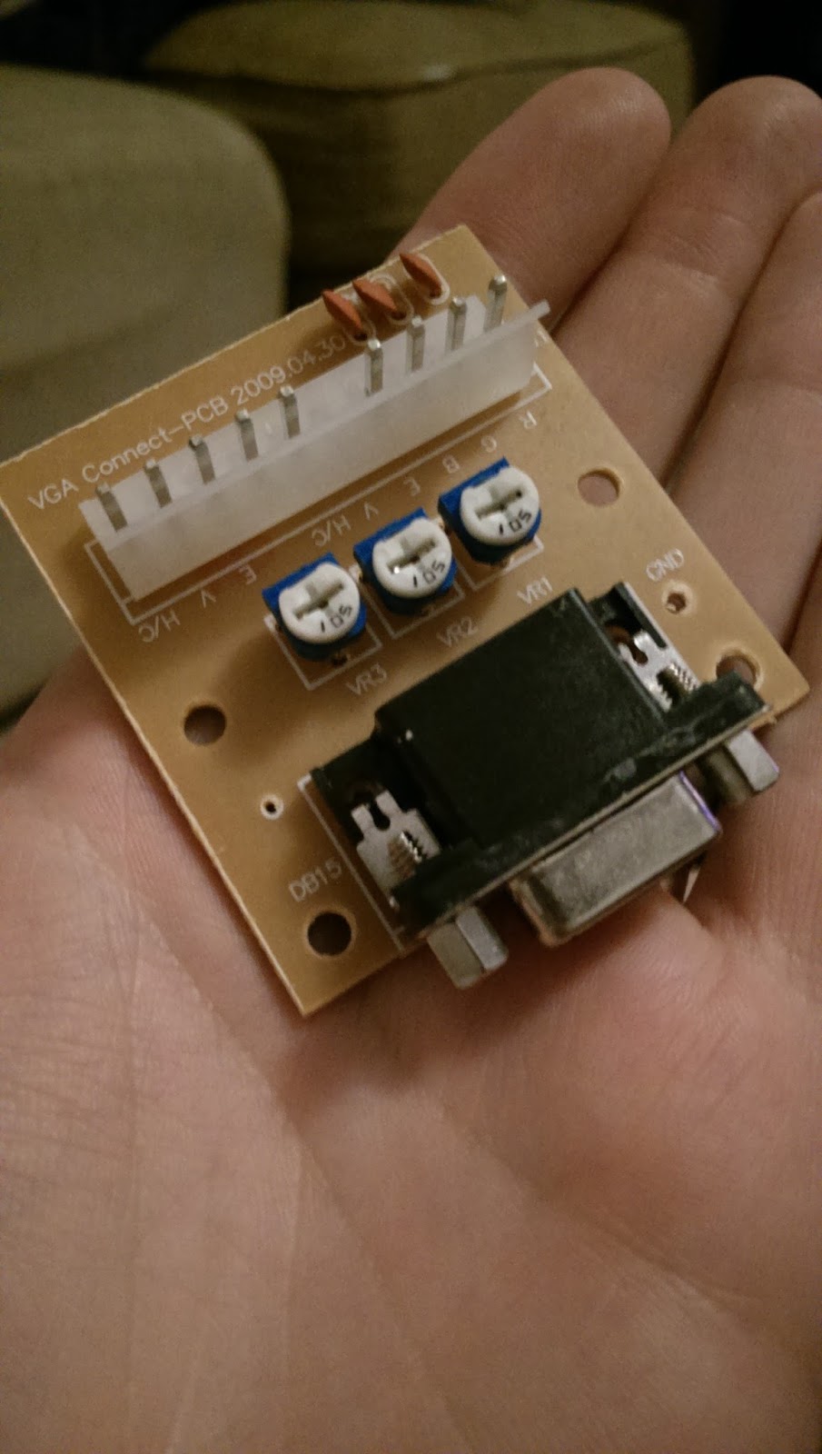
Either way, to get an image to show up, you'll need to use a compatible resolution and sync. On Windows this is achieved through a piece of software known as Soft15khz. In Linux, you can make it happen with the xrandr utility or by adding a custom modeline to your xorg.conf file (which probably doesn't even exist anymore; you'll have to create one from scratch, which is a bit of a hassle). You can also use a custom EDID, which is nice because it works with KMS consoles, but you'll have to recompile your kernel, nvm, you can specify custom EDIDs from GRUB (see this post for details). I went with the xrandr method, and I used a custom resolution of 1920x240. This aspect ratio may seem crazy, but CRTs don't really care what kind of horizontal resolution you feed them, so you can use a super-wide resolution like this and it will make fractional (i.e., non-integer) horizontal resolutions all look fine. 1920 also happens to be exactly 5x the 384 horizontal resolution of CPS-1/2, so Street Fighter games will be perfect. The JAMMA video standard calls for negative composite sync, so any custom modelines you create using modeline calculators (like this one) will need to end with "-HSync -VSync" in order for your monitor to sync up properly.

Once you finally get a picture, it should look something like this:
And that's pretty much it. I purchased an old marquee from eBay for $25 (it has some scratches, but it matches the cabinet's condition, so all the better) and printed out the bezel artwork from some high-res scans I found online. You can buy professionally printed repros for the bezel art, marquees and control panel overlays (CPOs), but they tend to cost as much as old stock for something as relatively new and common as Street Fighter games.

It's also worth noting that it's illegal to actually charge money to play games on a MAME machine, and you have to pay some taxes and be licensed to even accept quarters for any arcade game, so you'll need to hook up an extra button that goes to the coin mech to give yourself credits.

I have some additional woes with my monitor (including a failing flyback transformer, which causes the screen to get blurry, overbright and show horizontal retrace lines toward the top of the screen), which I will cover in another post, as they don't really relate to the subject at hand.

Update (9/15/2015): here are some shots of my repaired monitor playing some games at native res in RetroArch:

Friday, October 3, 2014

My Super Punch Out!! Arcade Cabinet

I just came into possession of an arcade cabinet. It's a genuine Nintendo Super Punch-Out!! cabinet from 1984 (i.e., almost as old as me).

Here it is, in its new (temporary) home on my covered back patio:
 The marquee is in good condition with just a few scratches and the speakers are still intact, surprisingly. The monitors look pretty terrible in that shot, but don't worry: that's not burn-in, just dirt and cigarette tar scuzz. The paint/vinyl on the sides has some cracking/chipping at the bottom and there's significant warping to the first few layers of plywood on top, but otherwise, it's pretty much intact, if dirty. Here's a shot of the inside, full of leaves:
 After applying equal parts rubbing alcohol and elbow grease, I got the dirt scum off the monitors to reveal some light-to-moderate burn-in on both monitors.
 But really, it's not so bad considering this old gal had nearly 50,000 games played on her, according to the analog counter inside (that's more than $10k in quarters; pretty good ROI!):
 The cabinet also came with a piece of smoked plexi that goes in front of the monitors (not pictured in the first image), and this plexi was covered with the same dirt/tar scum that coated the monitors, so it needed a deep-cleaning, as well. During the process, I took a before/after shot to illustrate how thick and nasty that stuff really was (ignore the basset hound on the floor fishing for belly-rubs):
Between the coating on the monitors and the coating on the plexi, I doubt anyone would have been able to tell whether it were turned on or not.

I haven't had a chance to get inside and poke around yet, but I plan to check the monitors' capacitors to see if they've leaked and/or dried out, which would necessitate recapping them, and I intend to pull the actual game boards and see if they've suffered any corrosion from on-board batteries. If all is well there, I'll try to actually plug it in--which will require attaching a new plug to the currently-bare wire-ends--and see if the transformer and power supply are still functional. I will also take apart and clean the coin doors, since they're a little janky, as well.

I'll update this post as I learn more :)

Update1:
I opened it up and was pleased to find that the batteries didn't seem to be terribly corroded:
I fitted a new plug onto the end of the bare wires, threw in some fresh batteries and powered it on. Everything seems to fire up okay, though there's not a lot of action:
At this point, I'm not sure if have a dicky connection to the board, a dead board or wiped eproms (their UV windows are uncovered and it's pretty bright inside my cabinet, due to the missing control panel). I know a guy who has an identical machine--in much better condition--who has offered to test the board for me, so that will be my next step, I think. In the meantime, I'll continue sprucing things up cosmetically.

Update2:
I drove my board out to test it in the aforementioned known-working cabinet and the results were less-than-great but better-than-bad:
The picture is blurry and there's a lot of glare on the plexi, but what you're looking at is some garbled graphics (no movement and no sound, unfortunately) and one perfectly-rendered '0'. This suggests to me that the board basically works--that is, it's not totally dead--but my eproms indeed need to be verified and my cabinet needs some more work to get even this far. I also need to go through and check all of my edge connectors and make sure the solder joints are secure and, if not, reflow them.

For the eproms, I'm hoping to borrow a USB programmer from a computer engineering professor at the university where I work. If that doesn't pan out, I can get one on eBay for $40.

Update3:
It was looking like getting SPO!! working was going to be more involved and expensive than I was really hoping to get into, and I didn't want to risk ruining a board that could actually make a collector very happy, so I traded the boards and cabinet to a really swell collector named Marv for this dandy of a JAMMA cabinet:
This is actually much more appropriate for my uses, since I can drop JAMMA boards in with ease (I intend to purchase a SF2: Hyper Fighting CPS-1 board in the near future) and, with the help of a J-PAC board, drop a MAME PC in with little-to-no modification. I'll be posting about this process soon.

Wednesday, June 22, 2011

Solder-less Happ Button Mod for Mad Catz SE Fight Stick

I actually performed this mod about a year ago on my own stick, but never published the pictures or process until now because I didn't think anyone would be interested. However, I've noticed a few threads on the Shoryuken forums with individuals asking for "clickier" alternatives to the sensitive-yet-mushy Sanwa and Seimitsu buttons that are currently preferred by most players, and Happ's products fill that niche quite nicely.

Before I dive in with the mod itself, I'm going to take a few moments to talk about differences between Japanese- and American-style arcade buttons and why someone might prefer one over the other. I'll try to be as objective as possible. If you already know or don't care, feel free to skip straight to the tutorial and pics.

Background

American-style buttons--specifically those from arcade part manufacturers Happ and IL--use a plunger positioned atop a Cherry microswitch, which produces a tangible and audible click when depressed. Japanese-style buttons, on the other hand, use a silent, low-resistance switch that provides little-to-no feedback as to when a button press is registered to the system. This is not to say that Japanese-style buttons are not sensitive, as they are actually significantly more sensitive than the Happ designs, there is simply no indication from the button itself as to when it will register.

Overall, Happ buttons seem to be popular with individuals who also like clicky, mechanical keyboards (like the venerable IBM Model M keyboard, which I use at home), as well as folks who grew up with the American arcade scene (i.e., "old farts," as the kids like to call us).

With that out of the way, lets get started. Some people have laughed at this mod for being "ghetto," but I'll take that over those tacky, overwrought custom sticks so many people seem to favor.

Anyway, as it says in the title, this is a solder-less mod, but you'll still need some additional items (Note: this is a button-only mod; putting a Happ stick into an SE is a much bigger undertaking and I don't recommend attempting it unless you are an experienced modder)

What You'll Need

1. Phillips-head screwdriver. To remove the screws from the bottom of the case.

2. Buttons. I recommend the Happ Competition pushbuttons, which have a low travel distance and convex shape, similar to Japanese-style buttons, but with that same satisfying click as the Happ Classics.

3. .187 quick-disconnects. These connect the stick's board to your buttons. The Japanese-style buttons use .110 quick-disconnects, which are too small for your mighty Happ buttons.

4. Wire. Somewhere around 14 to 16 gauge is good, even a little thicker or thinner should be fine, though you'll want to make sure your quick-releases can grab them properly.

5. Cardboard box. This will be used to make a spacer to provide room for your long-ass American buttons, which run deeper than their Japanese counterparts (/innuendo).

6. Glue. For the aforementioned spacer, which needs to be 2 layers deep. Pretty much any glue should be fine, but you want it to be pretty strong and thick. I used wood glue.

7. Optional. You can use special solderless connectors--like these--to join your wires to the stock wires, but I'll show you a little trick later on that works just fine without any connectors.

Step 1: Remove the bottom plate from the stick

Pretty self-explanatory. Just unscrew the 6 screws (2 in the middle and 1 under each of the 4 rubber feet).

Step 2: Trace the outline of the bottom plate onto your cardboard, twice
Depending on the size of your cardboard, you may have to break down your box. While you're at it, go ahead and draw a second square inside of each, about 1" smaller in each direction.

Step 3: Cut your cardboard

Cut along the lines you just drew such that you have 2x 1" frames of cardboard.

Step 4: Glue the frames together to make your spacer
Put your 2 frames together and glue them. This is your spacer, which provides the necessary clearance for your buttons.

For the next couple of steps, which cover removing the old buttons and putting the new ones in, I recommend replacing 1 button at a time so you don't get the wires mixed up. They're color-coded, but if you lose track of which wires go with which button, you'll have to do a bunch of trial-and-error testing at the end to get everything sorted out. Anyway...

Step 5: Pop out your stock buttons

They have a little clippy thing that holds them in:
If you press it in with a screwdriver or whatever, you should be able to pop them out without much trouble. Make sure you disconnect the wires from the bottoms first.

Step 6: Connect your new wires to the old button connectors

You can use the aforementioned optional solderless splicers or you can do what I did: strip the end of your new wire, pull back the rubber sleeve thing from the old .110 quick-disconnects, wrap your bare wire around the old quick-disconnects
and then slide the rubber sleeve over the whole thing. The connection will be fine and the sleeve will hold everything in place nice and tight. :D
Step 7: Add your new buttons

Not much to this step. Just stick 'em in there, screw on the included nut until it's tight and then clip in the included Cherry microswitch. It's a tight squeeze in the tiny SE case, so you'll want to take that into consideration. Take a look at my finished layout:
Step 8: Connect your buttons and test it out

Crimp your .187 quick-disconnects to stripped ends of your new wires and then connect them to your new Happ buttons. One wire connects to the bent post on the side of the microswitch and one connects to the nearest post on the bottom, as shown in the previous pic. Important: if the quick-disconnect on the side touches the bottom plate of your stick, it will ground itself and cause a button press to register (this is bad). To prevent it, you can tape/glue a piece of paper or plastic (I used one of those anti-static bags that an old computer motherboard was shipped in) to the inside of the plate, just to be extra-cautious.
At this point, you should be ready to test your buttons out. Make sure the wires are all connected to the correct button (i.e., the buttons execute the correct actions in-game). If any of them act like they're always pressed until you actually press the button (i.e., its response is backwards), then you've attached the wire to the wrong post.

Step 9: Replace the bottom plate

Once you're sure everything works properly, just cram your wires into place and screw the bottom back on. With the spacer, the screws should be just long enough to catch if you press firmly on the bottom plate. However, they probably won't be able to hold the rubber feet in place securely and you'll probably lose them (though I imagine most of you are like me and have long since lost those rubber feet anyway).

Here's what it looks like from the side. Yes, the cardboard is visible (though not particularly noticeable), and yes, people will probably make fun of you for it.
If you have any questions about the process, hit me up in the comments.

UPDATE: Reader sfkingalpha had the clever idea of covering the cardboard edge with duct tape, which greatly improves the appearance compared with nekkid cardboard:
"Aside from aesthetics, I think this also helps with air tightness and cardboard deterioration!"
Looks great, sfkingalpha!

He was also able to keep his rubber feet by getting longer screws, specifically 3/4 SS panheads.

Here's his finished product:

Friday, June 5, 2009

Conclusions and Helpful Links

Continued from Installing the Hardware

That's pretty much it. Just plug it up and give it a shot. If you find that any of your buttons are acting funny, e.g. nothing happens when you press the button until you let go, try swapping the locations of the wires around on the button (i.e., move the wire from the bent post to one of the straight ones and vice versa).

Once again, here's what the final product looks like:


I've presented my own experience here, but there are tons of others' experiences elsewhere online. The Shoryuken.com forums have some really great info on pad hacking and DIY stick-making. You can also find some great things at the arcadecontrols.com forums (HarumaN is an expert and sells pre-hacked pads at reasonable prices) and xbox-scene.com forums (RDC has some great, thorough information about pad hacking, along with some good tutorials on how to salvage pads after a screw-up).

Gamingnow.net sells damn-near anything a stick-builder could want, all at very reasonable prices.

MAMErs can purchase I-PAC interfaces from Ultimarc. Another option that seems to be preferred on the Shoryuken forums is the Cthulhu board, which can be purchased at gamingnow.net.

UPDATE: even better than the Cthulhu is Toodles' new Chimp board, which provides PC/PS3 support and is designed to accept a hacked 360 common ground pad to provide 360 support with automatic switching among protocols. Plus, it's cheaper than bare Cthulhus used to be! You can get it and other stick materials at Lizard Lick.

UPDATE 3/25/11: Even better than the Chimp board, now you can get the Akishop PS360 triple-mod board, which is a no-solder board that supports PS3, Xbox 360 and PC all at once. It costs slightly more (~$45), but it completely removes padhacking from the equation for the first time ever. This and other arcade stick parts intended for fighting game enthusiasts are available at focusattack.com.

If you want to build a standard, semi-low-profile stick similar to what you would buy in a store, I recommend checking out some of the articles on slagcoin.com. The site has TONS of great information about all aspects of stick-making, and their button layout section is unparalleled.

You can learn more about sticks--including the differences between various brands--here. The section about restrictor plates should be considered required reading for any aspiring stick-jockey.

Page 1: Building an Arcade-style Fight Stick
Page 2: Assembling Your Box
Page 3: Pad Hacking
Page 4: Installing the Hardware
Page 5: Conclusions and Helpful Links

Installing the Hardware

Continued from Pad Hacking

After the Hell that is pad hacking, this part is a breeze and is pretty straigtforward. You just put the buttons into the holes you cut in your panel, then screw down the plastic nut to hold them in place. At this point, I wouldn't bother screwing them down too hard because you might need to rearrange/rotate them later.

Next, attach your microswitches to the buttons. This picture shows a standard cherry microswitch that came with my arcade buttons.

When you go to attach the wires from your hacked pad to your microswitches, the best method is to use .187 sized quick releases (or .110 for japanese-style buttons) rather than soldering the wires directly to the posts, which will make repairing/replacing buttons much easier in the future.

For the joystick, you'll need to drill mounting holes around your large-diameter joystick hole. The Happ stick I chose is a top-mounted stick, but I wanted a smooth surface (i.e., no visible screw/bolt heads) so I countersank the holes a bit and then covered the bolts with wood glue and wood putty before staining/sanding.

This is a pretty permanent solution for better or for worse (no way to reposition the mounting bolts), but I intend to continue using Happ sticks in the future, so it shouldn't be too much of a problem.

After the glue and putty dried, I did a light sanding and proceeded to stain the top and sides.

Once that's all set, you can attach your joystick base by threading the mounting bolts through the appropriate mounting holes and then screwing the nuts onto the bolts. Once you have the base of the joystick bolted into place, follow the instructions that came with your joystick for dropping the stalk into place. The instructions for my Happ were not very clear, so I'll explain my process: first, put the plastic ring--textured side-up--on the stalk, followed by the plastic spacer, then push the stalk through the base until it pokes out the other side next to the microswitches. Next, take the actuator (that funky square piece) and PRESS IT DOWN until you can snap the little clip into place to hold it (the fact that it can be pressed down was not mentioned in my instructions and I erroneously thought the spacer was missized).

After that, you just need to attach your pad to the microswitches via the quick releases. The ground attaches to the side post and the signal attaches to one of the two straight posts on the bottom (one side registers when the button is pressed, the other registers until the button is pressed).


Here is how my first attempt ended up (not so hot):


And here's my second attempt (a little better):

At this point, I added a few extra touches, including hinges for the top to maintain easy access to the wiring and some cabinet handles on the back which also double as cable wraps:


Also, as you may have noticed in some of the previous pics, I attached some staples from a staple gun to the bottom of the box interior. I then used cable ties to stabilize the pads against the staples and keep them from flopping around whenever I move the box.


Page 1: Building an Arcade-style Fight Stick
Page 2: Assembling Your Box
Page 3: Pad Hacking
Page 4: Installing the Hardware
Page 5: Conclusions and Helpful Links

Analytics Tracking Footer